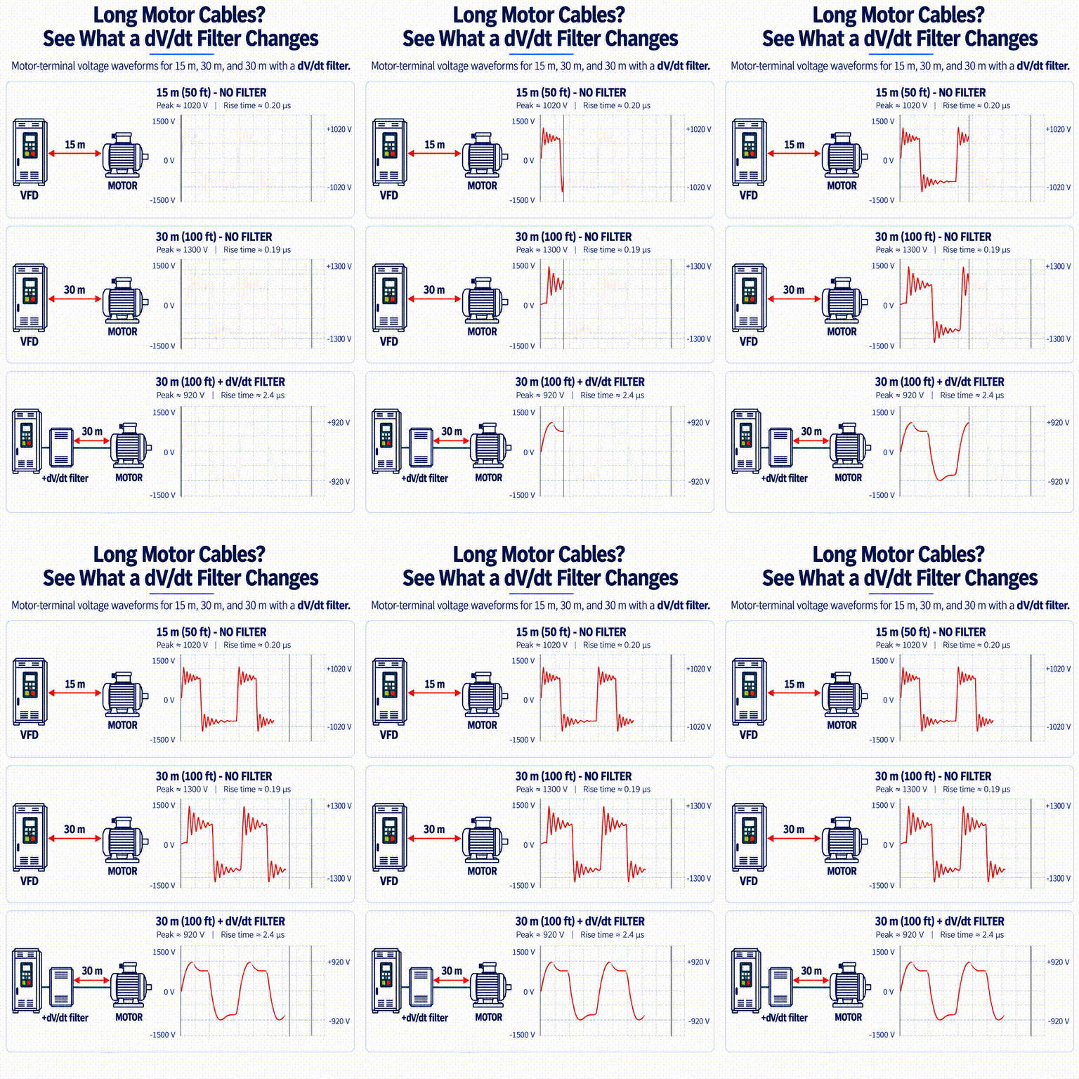
A VFD may generate a clean PWM pulse at its output terminals, but the waveform seen at the motor can be very different. As motor cable length increases, travelling-wave reflections between the VFD, cable, and motor can increase voltage overshoot and ringing at the motor terminals.
The animation above illustrates this effect using three example cases: a 15 m cable, a 30 m cable, and a 30 m cable with a dV/dt filter.
Cable Length Changes the Waveform
A VFD output pulse travels through the motor cable as a high-frequency travelling wave. When the wave reaches the motor, the difference between the cable impedance and the motor impedance causes part of the wave to reflect back toward the drive.
With a short cable, the reflected wave returns quickly and the resulting voltage distortion is relatively limited. As cable length increases, the travelling and reflected waves interact differently, producing greater overshoot and ringing at the motor terminals.
15 m Cable — No Filter
In the 15 m example, the motor-terminal waveform already shows some reflected-wave ringing.
For this test case:
- Peak voltage: ≈ 1020 V
- Rise time: ≈ 0.20 μs
The waveform still resembles the original PWM pulse, but the motor sees a voltage peak substantially higher than the steady pulse level.
30 m Cable — No Filter
Increasing the cable length to 30 m makes the reflected-wave effect more pronounced.
For this test case:
- Peak voltage: ≈ 1300 V
- Rise time: ≈ 0.19 μs
The fast rise time is essentially still present, but the voltage overshoot and ringing are significantly greater.
This is an important point: cable length does not simply “slow down” the PWM pulse. Instead, the cable behaves as a transmission line, and the interaction of incident and reflected waves can create a much higher motor-terminal voltage.
30 m Cable with a dV/dt Filter
A dV/dt filter changes the situation by slowing the voltage transition before the pulse travels through the long motor cable.
In the filtered 30 m example:
- Peak voltage: ≈ 920 V
- Rise time: ≈ 2.4 μs
The slower edge reduces the severity of the reflected-wave phenomenon. The waveform at the motor becomes smoother, ringing is reduced, and the peak motor-terminal voltage is substantially lower.
Why Rise Time Matters
The key parameter is not only cable length.
It is the relationship between:
VFD pulse rise time + cable propagation time + motor/cable impedance mismatch.
A very fast voltage edge contains more high-frequency energy and makes the cable behave increasingly like a transmission line.
That is why modern VFDs with very fast switching devices can create significant motor-terminal voltage stress even at cable lengths that may not appear particularly long.
What the dV/dt Filter Actually Does
A dV/dt filter does not simply reduce the RMS motor voltage.
Its main purpose is to reduce the rate of voltage change at the VFD output.
By increasing the rise time of the pulse:
dV/dt decreases → reflected-wave severity decreases → motor-terminal peak voltage decreases.
This can reduce electrical stress on the motor winding insulation, particularly in installations with long VFD-to-motor cables.
Engineering Takeaway
Long motor cables should not be evaluated only by voltage drop.
For VFD-fed motors, engineers should also consider:
- motor cable length
- pulse rise time
- switching characteristics
- reflected-wave peak voltage
- motor insulation capability
- whether an output reactor, dV/dt filter, or sine-wave filter is required
The three cases above show the basic trend clearly:
- 15 m: moderate reflected-wave effect
- 30 m: higher overshoot and ringing
- 30 m + dV/dt filter: slower rise time and significantly reduced motor-terminal stress
The voltage and rise-time values shown here are based on the specific ABB test examples used for this comparison. They should not be treated as universal values for every VFD, motor, or cable installation.