The Engineering Question
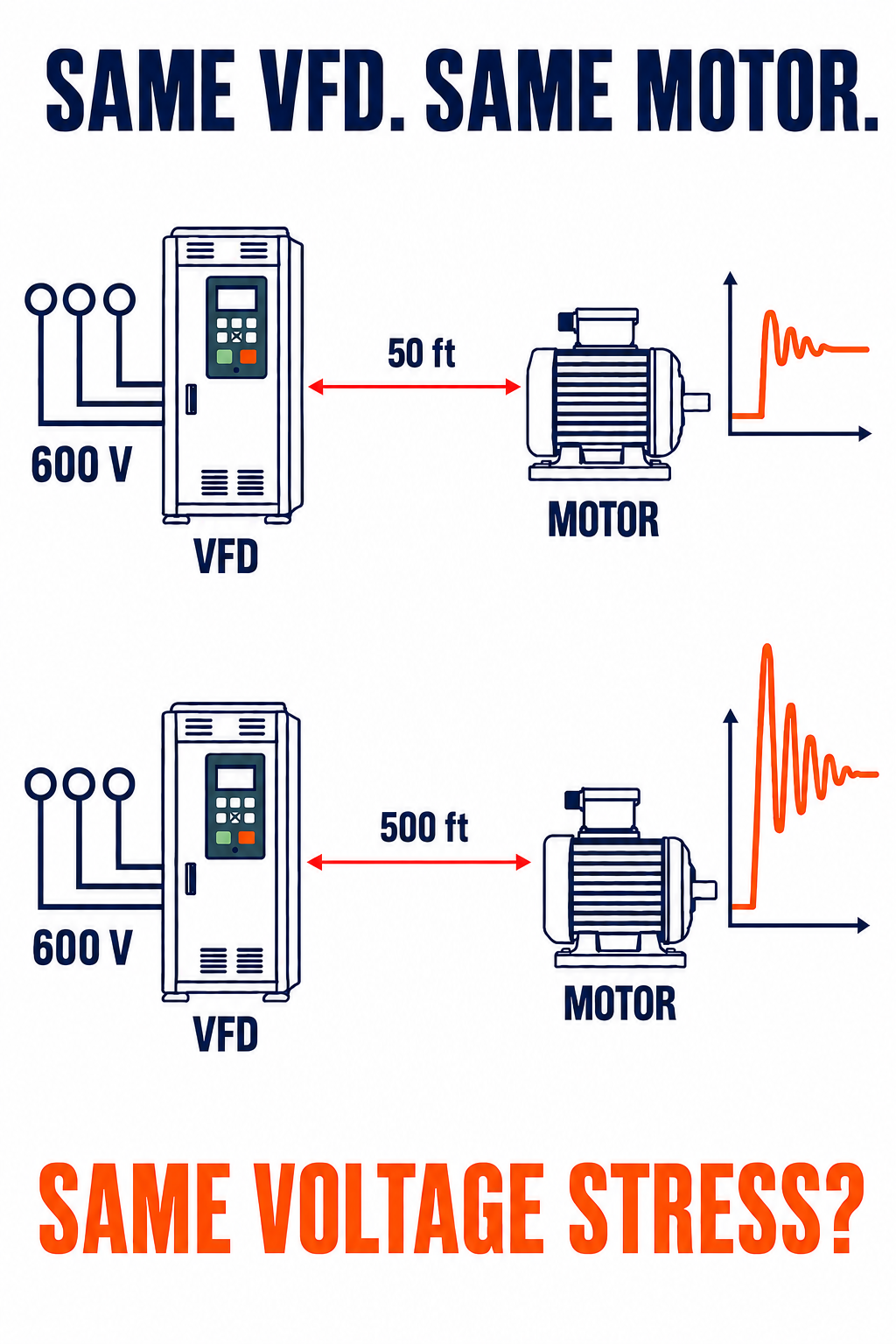
Consider two installations with the same 600 V variable-frequency drive (VFD), the same motor and the same mechanical load:
- Case 1: 50 ft of motor cable
- Case 2: 500 ft of motor cable
The drive has not changed. The motor has not changed. Yet the voltage waveform at the motor terminals can change substantially because the cable is part of the high-frequency electrical system.
At the fundamental motor frequency, a few hundred feet of cable may look like ordinary wiring with resistance, inductance and capacitance. At the very fast edges of a pulse-width-modulated waveform, however, the same conductors behave as a transmission line: voltage energy travels along the cable as a wave, encounters the motor, and can reflect.
Why PWM Is Not an Ordinary Sine Wave
A conventional sinusoidal supply changes voltage continuously. A modern VFD instead synthesizes the desired motor voltage and frequency by switching semiconductor devices and applying a sequence of voltage pulses. The motor current and air-gap flux can be approximately sinusoidal even though the instantaneous voltage at the drive output consists of steep-edged pulses.
The distinction matters because insulation stress is governed not only by RMS voltage. It is also influenced by:
- the peak voltage that reaches the motor terminals;
- the voltage rise time;
- the rate of change of voltage, or dv/dt;
- how often the pulses are applied;
- and how the voltage is distributed through the first turns of the winding.
Rise time is the interval over which a pulse edge moves between defined lower and upper voltage levels. A short rise time means a high dv/dt. ABB explains that the faster switching associated with IGBT drives can produce faster voltage rise and higher motor-terminal peaks, which is why the complete drive–cable–motor system must be considered [1].
The Cable as a Transmission Line
A fast voltage edge does not establish the same voltage instantaneously at every point along a long cable. It propagates from the VFD toward the motor at a velocity determined by the cable’s distributed inductance and capacitance and by the installation.
The important comparison is between:
- the pulse rise time; and
- the one-way and round-trip propagation time of the cable.
For an installed cable of length (l) and propagation velocity (v_p), the idealized travel times are:
Increasing cable length increases both times. The reflected wave therefore returns later relative to the incident edge. Whether the reflected and incident waves overlap—and how their instantaneous voltages add—depends on cable length, propagation velocity and the actual rise time of the drive pulse.
ABB Technical Guide 102 describes a critical cable length concept based on this timing relationship, but it also states that propagation velocity depends on cable type, conduit or tray and other installation details [2]. That is precisely why a single length cannot be used as a universal rule for every VFD system.
Impedance Mismatch and the Reflected Wave
Every transmission line has a characteristic or surge impedance. The motor also presents a high-frequency surge impedance that is not the same as its familiar low-frequency operating impedance.
When the incident voltage wave reaches the motor terminals, the mismatch between motor surge impedance (Z_m) and cable characteristic impedance (Z_c) determines the voltage reflection coefficient:
If the impedances were equal, the ideal reflection coefficient would be zero. With a mismatch, part of the wave is reflected back toward the VFD. A positive reflection adds to the incident voltage at the motor terminal. ABB notes that motor-cable characteristic impedance is typically lower than motor characteristic impedance and that the mismatch can be more pronounced for smaller motors [2].
The VFD end is another discontinuity. A returning wave can reflect again, travel back toward the motor and interact with later edges. Cable loss and other damping mechanisms reduce successive oscillations, but they do not make the first interaction disappear.
Why the Motor-Terminal Voltage Can Overshoot
The voltage measured at the VFD output terminals is the launched PWM waveform at the source end of the cable. The motor-terminal voltage is the local sum of incident and reflected waves at the load end. Those two locations therefore need not show the same peak or edge shape.
In the 50 ft case, the propagation interval is shorter. In the 500 ft case, the longer travel and return times change the timing of wave superposition. Under some combinations of rise time and impedance mismatch, the incident edge may have substantially developed before its reflection returns, allowing a larger local overshoot at the motor.
This is not a claim that every 500 ft installation has a specific peak, nor that every 50 ft installation is benign. ABB’s guidance identifies motor-lead length and cable impedance as primary factors, while also listing motor insulation rating, motor and drive impedances, switching behavior and input voltage as relevant variables [1].
What Causes the Decaying Ringing?
The cable, motor and drive output contain distributed and lumped inductance and capacitance. Together they can form an underdamped high-frequency network. A fast switching edge excites that network, producing oscillation around the new voltage level.
The oscillation decays because energy is dissipated in conductor resistance, dielectric loss, motor loss, the drive and any intentionally added damping. Its frequency, amplitude and decay rate are system properties—not constants that can be inferred from nominal voltage and length alone.
Reflected-wave overshoot and ringing are related but not identical descriptions:
- Reflection describes waves produced by impedance discontinuities.
- Ringing describes the damped oscillatory response of the cable–motor–drive network.
- In a real installation, they can occur together and shape the same motor-terminal pulse.
ABB Technical Guide 102 explicitly describes the cable, motor and output circuit as a potential resonant circuit and relates motor-terminal peaks to cable length, motor surge impedance, rise time and switching frequency [2].
Why Longer Cable Can Increase Insulation Stress
Longer cable does not create energy by itself. It changes the propagation delay, distributed capacitance and the timing of reflections. That can change both peak motor-terminal voltage and dv/dt.
Fast-rising voltage can be distributed unevenly through a winding, concentrating stress near the line-end turns. Repeated high-frequency pulses can therefore challenge turn-to-turn and phase insulation even when the motor’s RMS operating voltage appears normal. The concern is the combination of peak magnitude, rise time, repetition and the insulation system’s capability and condition.
ABB also cautions that the result cannot be determined precisely from the drive waveform and cable length alone: conductor size, cable type, conduit and motor characteristics influence the result [2]. Thermal aging, contamination, moisture, previous rewinding and the motor’s actual insulation design can further change the available margin.
Variables That Control the Result
| Parameter | Why it matters |
|---|---|
| Drive rise time | Faster edges contain more high-frequency content and make transmission-line effects relevant at shorter propagation intervals. |
| Cable length and propagation velocity | They set one-way and round-trip travel time and therefore the timing of wave superposition. |
| Cable characteristic impedance | Along with motor surge impedance, it determines the magnitude and polarity of reflection. |
| Motor surge impedance | Motor size, winding and construction affect the impedance mismatch at the cable termination. |
| Cable construction | Geometry, insulation, shielding and conductor arrangement affect distributed inductance, capacitance, loss and propagation. |
| Grounding and shield termination | High-frequency return-path impedance influences common-mode current, emissions and the measured waveform. |
| Switching frequency and control | They influence pulse repetition, losses and the opportunity for ringing from one event to interact with later switching events. |
| Installation conditions | Parallel cables, splices, junctions, cable trays, conduit, output contactors and routing can introduce discontinuities or change cable behavior. |
| Line and DC-bus conditions | The launched pulse magnitude follows the drive’s actual DC-link and switching state, not only the motor nameplate voltage. |
Grounding deserves special attention. A low-impedance, high-frequency bonding and shield-termination scheme is required for EMC and bearing-current control, but it does not by itself eliminate differential-mode reflected-wave voltage at the motor. The drive manual’s cable and grounding instructions remain part of the filter decision.
Drive Output vs. Motor Terminals
| Location | What the waveform represents |
|---|---|
| VFD output terminals | The inverter’s launched PWM pulses plus any local interaction with returning waves and the output network. |
| Motor terminals | The incident wave plus local reflections and ringing at the end of the installed cable. |
An instrument connected at the drive cannot be assumed to report the motor-terminal peak. Conversely, measurements at a 600 V PWM motor circuit require probes, bandwidth, grounding technique, category rating and safety procedures suitable for the actual common-mode and differential-mode voltages. Probe or connection errors can create misleading ringing or expose personnel and equipment to serious hazards.
Comparing the Mitigation Options
The names load reactor, dv/dt filter and sine-wave filter describe different levels of output-waveform treatment. They are not interchangeable, and a product’s allowed drive frames, currents, cable lengths, switching frequencies, output frequencies and enclosure arrangements must be verified in the applicable manuals.
| Option | Typical location | Primary effect | Key limitations |
|---|---|---|---|
| Load reactor | Series-connected at or near the VFD output, using a reactor specifically rated for PWM output duty. | Adds inductance, slows the edge and can increase the cable length over which a reflection develops fully. | Does not necessarily clamp the motor-terminal peak; adds voltage drop, loss, heat and space requirements, and can be ineffective when the installed cable remains electrically long relative to the modified rise time. |
| dv/dt filter | At the VFD output or in a nearby enclosure, as specified by the filter and drive manufacturer. | A damped low-pass network increases rise time and reduces dv/dt and motor-terminal overshoot more deliberately than a reactor alone. | Does not produce a utility-quality sine wave; has model-specific current, frequency, cable, thermal and installation limits and may require drive parameter settings. |
| Sine-wave filter | At the VFD output, normally close to the drive and installed with the prescribed cable and cooling clearances. | Attenuates the PWM carrier so the motor receives a waveform much closer to sinusoidal, greatly reducing fast-edge and reflected-wave excitation. | Larger, more expensive and more lossy; introduces voltage drop and resonance constraints; requires compatible drive control settings and limits on switching/output frequency and application type. |
Load Reactor
An output load reactor is a series inductor designed to carry the drive’s PWM current. It should not be confused with an input line reactor: ABB warns that an input reactor is not automatically suitable at a VFD output because the output harmonic spectrum and insulation duty differ [2].
The added inductance reduces edge steepness. This can reduce reflected-wave stress if the new rise time makes the installed cable electrically short enough. It is not a universal peak-voltage limiter. ABB notes that if the cable remains longer than the effective critical length, the motor can still experience the peak associated with reflection; the reactor also introduces voltage drop and may affect available motor voltage and torque [2].
A load reactor is therefore a candidate when the applicable drive documentation permits it and a moderate reduction in dv/dt or cable-charging current is required. Selection requires output-duty ratings, continuous current, fundamental frequency, switching behavior, thermal conditions and expected voltage drop—not cable length alone.
dv/dt Filter
A dv/dt filter is designed specifically to slow the voltage transition and damp high-frequency content. ABB describes its filter arrangement as a damped low-pass network installed at the drive output [2]. By lengthening rise time and damping the edge, it directly targets the conditions that produce motor-terminal overshoot.
It remains a PWM-output solution rather than a full sine-wave reconstruction filter. Its effectiveness and permissible motor-cable length are product-specific. ABB’s current ACS880 guidance uses decision flowcharts that consider drive voltage and frame, motor type and insulation, cable construction and length, and application conditions; those charts are recommendations for the covered ACS880 products, not universal VFD rules [1].
The relevant hardware and firmware manuals must also be checked. ABB documentation, for example, identifies a drive setting for an external dv/dt filter because the setting can affect switching behavior and cooling [3].
Sine-Wave Filter
A sine-wave filter uses an LC or related low-pass network to remove most of the switching-carrier content before the motor cable. Because the cable is no longer excited by the same steep PWM edges, reflected-wave and dv/dt stress at the motor can be substantially reduced.
This is the most comprehensive of the three waveform treatments, but also the most application-sensitive. Filter resonance, reactive current, voltage drop, thermal loading, output-frequency range, drive modulation and commissioning parameters matter. ABB’s ACS880 control documentation requires sine-filter support settings and explains that ABB-filter operation can limit switching and output frequencies to avoid resonance and overheating [3]. ABB also publishes a dedicated application note for sine filters used with ACS880 drives [4].
A sine-wave filter may be considered for very long motor leads, older or sensitive motors, low motor acoustic noise, reduced motor losses, or applications in which a near-sinusoidal motor voltage is specifically required. Those are engineering reasons to evaluate the option—not permission to apply an arbitrary filter to any 600 V drive.
A Selection Workflow for the Two Cases
For both the 50 ft and 500 ft examples, use the same disciplined sequence:
- Identify the exact VFD type code, voltage class, frame, switching settings and braking mode.
- Obtain the drive manual’s maximum motor-cable guidance and approved output-filter tables.
- Confirm the motor’s allowable peak terminal voltage and rise-time or dv/dt capability with the motor manufacturer, including any effect of age or rewind history.
- Record cable type, conductor arrangement, shield, grounding, length, parallel runs, splices, contactors and installation environment.
- Check cable capacitance and charging-current limits as well as insulation stress; the longest permitted cable may be governed by drive loading, EMC or protection behavior rather than reflected voltage alone.
- Select only a reactor or filter compatible with the exact drive and application, and apply all required derating, parameter and cooling instructions.
- Where the available documentation does not resolve the case, obtain a manufacturer application review or perform a properly specified study or measurement.
What the 50 ft vs. 500 ft Comparison Actually Shows
The comparison makes one controlled change: cable length. Electrically, that change also changes propagation time and distributed cable parameters. It therefore changes the conditions under which the motor sees incident waves, reflected waves and ringing.
The defensible conclusion is qualitative:
- the motor-terminal waveform is not necessarily the same as the drive-terminal waveform;
- longer cable can increase the opportunity for reflected-wave overshoot and insulation stress;
- but the actual peak, rise time and required mitigation cannot be inferred from length alone.
No universal statement such as “all cables beyond a particular length require a dv/dt filter” is technically valid across all VFDs. Even ABB’s product-specific tables and flowcharts must be read with their stated scope, assumptions and notes.
Conclusion
The VFD controls the launched PWM waveform, but the cable and motor determine what happens after each fast edge leaves the inverter.
At the motor terminal, an impedance mismatch produces reflection. Cable length sets the travel time. Distributed inductance and capacitance create an oscillatory network. Damping makes the ringing decay. The resulting peak voltage and dv/dt can differ from what is observed at the drive output, and repeated stress can challenge the motor insulation.
A load reactor, dv/dt filter and sine-wave filter address progressively more of the fast-edge waveform, but each introduces its own constraints. The correct choice is an application decision based on documented compatibility—not a reaction to cable length in isolation.
References
References
- [1] ABB Technical Note 181 — Selecting and Applying Output Filters: For use with ACS880 480 V and 600 V drives, Rev. D.
- [2] ABB Technical Guide No. 102 — Effects of AC Drives on Motor Insulation.
- [3] ABB — ACS880 Primary Control Program Firmware Manual, sections on external dv/dt filter and sine-filter support.
- [4] ABB Technical Note 086 — Sine Filters Used with ACS880 Drives.
- [5] ABB — ACS880-01 Hardware Manual, motor-insulation and output-filter planning guidance.