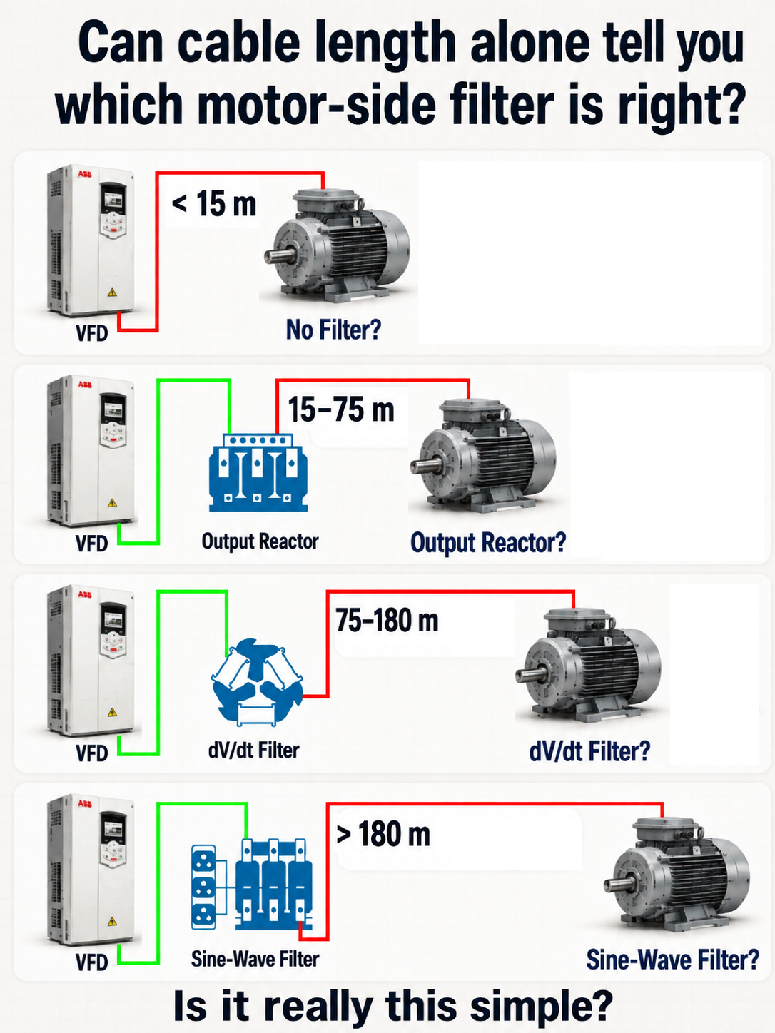
The rule is useful. The system decides.
A familiar field rule sorts VFD motor leads into four distance bands:
- short cable: no added device;
- longer cable: output reactor;
- longer again: dV/dt filter;
- very long cable: sine-wave filter.
That sequence is useful because engineering happens in the real world. Service technicians, panel builders, OEMs, and drive specialists need repeatable starting points. A distance rule can compress years of experience with one drive family, voltage class, motor type, cable, and switching-frequency range into a fast screening decision.
The problem starts when a rule of thumb quietly becomes a design law.
The distances in the article image—less than 15 m, 15–75 m, 75–180 m, and more than 180 m—are illustrative only. They are not ARTPHASE limits, manufacturer recommendations, or boundaries that transfer unchanged between 208 V, 480 V, and 600 V systems.
This note focuses on choosing the mitigation. For the transmission-line mechanism itself, first see Why VFD motor cable length changes motor-terminal voltage stress.
Why cable-length rules exist
Cable length is an unusually practical proxy. It is easy to measure, appears on drawings, and correlates with propagation delay, distributed capacitance, inductance, charging current, voltage drop, and EMC exposure. Within a known product ecosystem, a manufacturer may have already tested enough combinations to publish usable lead-length tables or decision charts.
A field threshold can therefore be entirely reasonable when the following remain substantially unchanged:
- VFD family, frame, modulation, and voltage class;
- motor type and documented insulation capability;
- cable construction, routing, grounding, and number of parallel runs;
- carrier-frequency range and motor operating-frequency range;
- installation topology and the manufacturer’s approved mitigation devices.
It supports speed, repeatability, conservative practice, and consistent builds. Its limitation begins when any of those hidden assumptions changes—or when nobody can say what the assumptions were.
ABB’s output-filter guidance demonstrates this directly. Its ACS880 selection flowcharts branch on 480 V versus 600 V, drive frame, motor insulation, cable length, motor type, and special configurations; they are recommendations for the covered ACS880 products, not a generic VFD standard [1, pp. 3–8]. Danfoss likewise states that maximum motor-cable length depends mainly on switching frequency, DC-link voltage, and cable setup, and then applies a total-capacitance condition when cables are paralleled [5, sec. 7.1].
Two different cable problems must stay separate
“Long cable” can describe a fundamental-frequency voltage-drop problem, a high-frequency PWM problem, or both. Treating them as one calculation causes bad selections.
| Question | Primary variables | Typical consequence |
|---|---|---|
| Fundamental 50/60 Hz voltage drop | Load current, conductor resistance and reactance, route length, motor frequency, power factor, temperature, conductor size, and filter impedance | Reduced motor voltage and torque margin; extra current, heating, and losses |
| High-frequency PWM/reflected-wave behavior | DC-bus level, edge rise time, propagation time, surge-impedance mismatch, distributed L and C, cable construction, topology, and termination | Motor-terminal overshoot, winding stress, cable charging current, ringing, EMC, common-mode, and bearing-current concerns |
A larger conductor can improve fundamental voltage drop. It does not automatically cure reflected-wave stress; changing conductor geometry can also change characteristic impedance and capacitance. Conversely, a motor-side filter may reduce high-frequency stress while adding fundamental voltage drop and heat that must be included in motor and drive sizing.
Why length alone is insufficient
At a fast PWM edge, the cable behaves as a transmission line. Its one-way travel time is approximately (l/v_p), where (l) is route length and (v_p) is propagation velocity. Whether a reflection returns while the launched edge is still rising depends on both travel time and the VFD’s actual edge rise time. The reflection magnitude depends on the high-frequency impedance mismatch between cable and motor—not simply on metres or feet.
The decision therefore changes with:
- Nominal voltage and actual DC bus. They establish the scale of the launched pulse and the available motor-insulation margin.
- VFD topology and family. Semiconductor generation, modulation, frame size, rise time, control mode, braking condition, and permitted output networks differ.
- Carrier frequency. It influences filter loss, cable charging, repeated stress, and product operating envelopes. It is not interchangeable with edge rise time.
- Cable construction. Shielding, geometry, insulation, conductor arrangement, tray/conduit, and grounding affect propagation, characteristic impedance, capacitance, inductance, common-mode paths, and EMC.
- Motor evidence. “Inverter duty” is useful only when backed by a stated peak-voltage/rise-time capability and applicable standard or manufacturer data. Age, contamination, moisture, repair, and rewind history can reduce confidence.
- Topology. Parallel cable runs and multiple motors increase cumulative capacitance and create branches and impedance discontinuities. Output contactors, junctions, and splices also matter.
- Application. Submersible and borehole pumps can combine very long leads, high cable capacitance, difficult access, and special motor insulation. High-speed motors can exceed a filter’s allowed fundamental output frequency.
- Other objectives. Differential-mode reflected-wave mitigation, common-mode voltage, bearing current, radio-frequency emissions, and fundamental voltage drop are not one requirement. One filter does not necessarily solve all of them.
ABB’s dU/dt-filter manual makes the topology issue concrete: its 300 m maximum for several filter families is cumulative for several parallel-connected motors, and selection must use total cable capacitance [2, pp. 14–15]. Danfoss’s iC7 guidance similarly bases limits on the prescribed number of parallel cables and requires derating when cable capacitance or cable count differs [5, sec. 7.1].
Why 208 V, 480 V, and 600 V are not the same problem
The reflected-wave mechanism can occur at every voltage class. A 208/230 V system is not immune. What changes is the absolute launched voltage, possible peak stress, applicable insulation requirement, and product-specific filter envelope.
For a conventional six-pulse front end under idealized steady conditions, engineers often use this rough relationship:
That gives illustrative DC-bus scales of about 294 V at 208 V, 679 V at 480 V, and 849 V at 600 V. A strongly positive reflection can make a local motor-terminal step approach roughly twice the incident step in an idealized transmission-line picture.
Manufacturer guidance shows why voltage class matters:
- ABB’s ACS880 note uses different decision paths for 480 V and 600 V drives and distinguishes standard from form-wound motors [1, pp. 3–8].
- Danfoss publishes progressively higher motor-insulation values across nominal-mains bands: 1300 V at up to 420 V, 1600 V above 420 through 500 V, 1800 V above 500 through 600 V, and 2000 V above 600 through 690 V for the covered product guidance [6, table 10.18].
- HPS rates the cited Centurion D family for 480–600 V applications and instructs users to consult HPS for applications below 480 V rather than declaring that lower-voltage systems never need filtering [3, pp. 4–5].
- TCI’s V1K brochure covers 208–600 V, but its carrier-frequency, current, lead-length, and fundamental-frequency limits still apply [4, p. 2].
The defensible conclusion is not “600 V always needs a filter” or “208 V never does.” Higher voltage generally reduces insulation margin for a given insulation system and waveform, but the correct boundary remains system- and manufacturer-specific.
What an output reactor does—and does not do
On the motor side, use output reactor or load reactor. “Line reactor” normally identifies the VFD input-side function. Some products, including MTE RL and TCI KDR/KLR families, are explicitly marketed by their manufacturers for both line and load service; that manufacturer terminology does not erase the difference in application [7][8].
An approved output reactor adds series inductance. It can moderate current change, lengthen the voltage edge seen by the cable, reduce cable-charging current, and reduce motor-terminal peak voltage in a suitable application. MTE describes its IGBT-protected load use for reducing dV/dt and peak voltage on long motor leads [7]. HPS describes output-side use as moderating transients seen by the motor [9, pp. 2–4].
It does not:
- reconstruct a sine wave;
- guarantee a particular motor-terminal peak on every cable;
- make motor-lead length unlimited;
- automatically address common-mode or bearing-current objectives;
- qualify an input-only reactor for PWM output duty.
If the reactor-lengthened edge is still fast compared with cable travel time, substantial reflection can remain. Added impedance also means voltage drop, watts loss, heat, enclosure space, and possible loss of motor torque margin. Fundamental output frequency, continuous and overload current, PWM insulation duty, ambient temperature, and the exact drive manufacturer’s permission must be checked.
Calling a reactor “a small dV/dt filter” hides an important design distinction. A purpose-designed dV/dt filter normally adds a damping network and a defined performance envelope; a reactor alone is predominantly series inductance.
What a dV/dt filter changes
A dV/dt filter is a damped low-pass output network intended to increase rise time, reduce the rate of voltage change, damp ringing, and limit motor-terminal peaks. It targets the PWM edge while leaving a recognizably pulsed voltage waveform at the motor. It is therefore not equivalent to a sine-wave filter.
The application envelope is part of the product:
- ABB’s NOCH/AOCH manual limits average switching frequency to 3 kHz below 500 V and 2 kHz above 500 V for the covered filters; maximum drive-to-filter cable is 3 m; allowed motor-cable length varies by filter type and can be 150 or 300 m; output frequency is limited to 120 Hz [2, p. 15].
- HPS Centurion D lists 2–4 kHz inverter switching, up to 60 Hz output, up to 1000 ft lead length in specified models, and selection by motor full-load current. Its notes say cable type affects maximum lead length and that its selection lengths include an allowable-voltage-drop criterion [3, pp. 4–7].
- TCI V1K lists 2–4 kHz carrier frequency, up to 1000 ft lead length with factory consultation above that, and 0–60 Hz fundamental output with derating up to 120 Hz [4, p. 2].
- Danfoss recommends the covered dU/dt filters only through 150 m and its sine-wave filters above 150 m, but that statement belongs to the VLT FC/VLT 5000–8000 filter family in that design guide—not every drive [10, sec. 3.2].
These values are not interchangeable. They use different circuits, test conditions, voltage scopes, cable assumptions, current ratings, and selection rules. Installation is normally close to the VFD, but the exact maximum VFD-to-filter distance comes from the filter manual.
What a sine-wave filter changes
A sine-wave filter uses inductance and capacitance as a low-pass network to attenuate the PWM carrier so the motor-terminal voltage is much closer to sinusoidal. Danfoss explicitly distinguishes this from a dU/dt filter, whose task is to reduce pulse-edge steepness [11]. ABB describes its ACS800 filters as low-pass networks that suppress high-frequency components [12, p. 13].
Removing most carrier content can reduce reflected-wave excitation, motor insulation stress, motor switching noise, and high-frequency motor losses. Danfoss also reports reduced bearing stress, while carefully noting that the cited differential-mode sine filter does not act between motor phases and ground and that leakage current can still limit motor-cable length [10, sec. 3.2.2]. That qualification matters: “sine wave at the motor” does not mean every common-mode and EMC problem has disappeared.
A sine-wave filter is not simply “the strongest dV/dt filter.” It changes the waveform more fundamentally and introduces its own operating constraints:
- LC resonance and required drive parameter/control-mode settings;
- current rating, reactive current, loss, cooling, and voltage drop;
- carrier-frequency and minimum-carrier requirements;
- maximum motor frequency and field-weakening restrictions;
- cable capacitance and leakage-current limits;
- multi-motor and parallel-cable rules;
- restrictions on special motors and regenerative/topology combinations.
ABB’s ACS800 manual illustrates the trade-off. It reports product-specific voltage drop, states that 60 Hz drop is about 20% higher than at 50 Hz, discourages operation above field weakening and high overloads, and requires the documented sine-filter parameter setting [12, pp. 13–14]. For that particular ACS800/filter combination it says cable length after the filter is not limited, but immediately requires the additional long-cable voltage drop to be included in sizing [12, p. 14]. That is not permission to generalize “unlimited cable” to other products.
Very long submersible leads are a common reason to evaluate a sine-wave filter because access is difficult and the application may combine an unknown motor insulation system with substantial cable capacitance. Manufacturer review is still required; the longest distance band does not select a part number.
Published guidance does not collapse into one distance table
The table below is deliberately not an apples-to-apples ranking. It shows how each manufacturer defines a different, conditional operating envelope. The disagreement is useful evidence: the distances belong to products and conditions, not to the generic names “dV/dt filter” or “sine-wave filter.”
| Manufacturer / family | Published guidance | Conditions that control interpretation | Locator |
|---|---|---|---|
| ABB NOCH/AOCH dU/dt filters | Filter-specific 150 or 300 m maximum; 300 m cumulative where several motors are connected in parallel | Covered filter types; 3 m maximum drive-to-filter cable; average switching limit 3 kHz below 500 V or 2 kHz above 500 V; 120 Hz maximum output | Manual 3AFE58933368, pp. 14–15 [2] |
| ABB ACS800 sine filters | Cable after the covered filter stated as not length-limited | Only listed ACS800/filter combinations; long-cable voltage drop still controls sizing; parameter, control-mode, torque, and frequency restrictions apply | Manual 3AFE68389178 Rev. G, pp. 13–14 and rating tables [12] |
| Danfoss VLT FC dU/dt and sine-wave filters | dU/dt recommended through 150 m; sine-wave above 150 m | Covered VLT filter/drive families and guide conditions; cable capacitance, leakage current, switching frequency, and parallel runs still matter | MG.90.N1.02, sec. 3.2 [10] |
| HPS Centurion D | 600 ft and 1000 ft models; up to 1000 ft listed | 480–600 V application scope; 2–4 kHz switching; up to 60 Hz output; VFD cable recommended; voltage-drop note and current selection apply | Brochure, pp. 4–7 [3] |
| TCI V1K | Up to 1000 ft; consult factory above 1000 ft | 208–600 V, 2–4 kHz standard carrier envelope, current rating, cable length, and 0–60 Hz fundamental; derating/consultation conditions apply | Brochure v3.0 (2025), p. 2 [4] |
| MTE RL line/load reactor | No universal distance published on the cited product/application pages | MTE confirms output-side IGBT-protected application and mitigation of long-lead effects; exact reactor sizing and VFD compatibility remain required | MTE RL product and application pages [7][8] |
This comparison also explains why an honest article should not invent a clean 15/75/180 m “industry standard.” Even where two brochures both say 1000 ft, the filter topology, voltage range, carrier rules, voltage-drop basis, performance target, and factory-consultation gates are not necessarily the same.
A practical decision framework
Use cable length to start the review, then run the following gates in order.
- Identify the exact VFD. Record manufacturer, family, type code, frame, voltage class, front-end/regenerative topology, control mode, braking arrangement, and firmware.
- Identify the motor evidence. Record voltage, current, construction, winding/insulation data, inverter-duty basis, allowable peak and rise time if published, age, rewind history, bearing arrangement, and whether the motor is submersible or high speed.
- Map the cable topology. Record one-way route length, cable type, shield and termination, conductor arrangement, capacitance per length, number of parallel runs, branches, multiple motors, output contactors, and junctions. Use cumulative capacitance where the manufacturer requires it.
- Check the VFD manual first. Find maximum motor-lead tables, EMC conditions, capacitance limits, insulation guidance, approved output devices, derating, and required parameters for the exact family.
- Check PWM information. Confirm allowable and configured carrier frequency. Obtain edge rise time or manufacturer application guidance where available. Do not infer rise time from carrier frequency.
- Evaluate high-frequency and common-mode objectives separately. Determine whether the concern is differential reflected voltage, cable-charging current, common-mode voltage, bearing current, EMC, or a combination.
- Check fundamental performance separately. Calculate cable and filter voltage drop, motor terminal voltage, torque margin, drive loading, filter loss, heating, and enclosure cooling across the operating-frequency range.
- Screen mitigation candidates. Consider no added mitigation, an approved output reactor, a dV/dt filter, or a sine-wave filter based on the actual objective—not on a presumed hierarchy.
- Verify the exact device envelope. Match voltage, current and overload, carrier frequency, motor frequency, cable capacitance/length, installation distance, ambient, enclosure, multi-motor rules, topology, and required parameters.
- Record assumptions and stop gates. Identify missing data and whether the unresolved item requires a motor, VFD, cable, or filter manufacturer review.
| Outcome | Appropriate meaning |
|---|---|
| No mitigation supported | The exact drive guidance, motor evidence, cable topology, and operating settings support the installation without an added motor-side device. |
| Output reactor candidate | An approved PWM-output reactor appears sufficient for the documented objective, subject to loss, drop, frequency, thermal, and compatibility checks. |
| dV/dt filter candidate | Edge-rate and peak-voltage mitigation are required, and a product exists whose complete envelope covers the installation. |
| Sine-wave filter candidate | Near-sinusoidal motor voltage or a specific very-long-lead/sensitive-motor objective is justified, and all LC-filter restrictions can be met. |
| Manufacturer review required | The topology is special, a documented limit is exceeded, or the manual explicitly calls for consultation. |
| Insufficient information | A critical fact—often exact VFD, motor insulation, cable capacitance/topology, or operating frequency—is missing. Do not issue a definitive selection. |
Five conceptual cases
Case A — 480 V, short cable, modern inverter-duty motor
The initial screen may support no added device, but only after confirming the exact drive’s lead-length guidance, the motor’s actual inverter-duty basis, configured carrier frequency, cable construction, and EMC/bearing requirements. “Short” does not override a drive manual or weak insulation evidence.
Case B — 480 V, long shielded cable, insulation unknown
Shielding supports an EMC return path when correctly terminated but often increases cable capacitance. The unknown motor insulation is a decision gate. Obtain motor data, total cable capacitance, and the drive’s approved dV/dt/sine-wave options. A dV/dt filter may be a candidate; a final selection is not supportable from length alone.
Case C — 600 V, long motor cable
The mechanism is the same as at lower voltage, but absolute pulse stress and insulation margin demand closer review. Use the 600 V path in the exact drive documentation, verify the motor’s peak/rise-time withstand, and respect the lower carrier limit if the chosen filter specifies one. ABB’s cited NOCH/AOCH manual, for example, distinguishes switching-frequency limits above 500 V [2, p. 15].
Case D — 208/230 V, long cable
Do not declare “no filter” merely because the DC bus is lower. Cable charging, nuisance trips, EMC, common-mode behavior, motor condition, and reflected voltage still exist. Some filter families cover this voltage; others direct the user to the manufacturer. The decision may be no mitigation, an output reactor, a filter, or manufacturer review depending on the exact system.
Case E — very long submersible-pump lead
Collect downhole motor insulation data, full lead topology and capacitance, output frequency range, voltage-drop/starting-torque margin, grounding, and manufacturer limits. Sine-wave filtering is often evaluated for this class of application, but the filter’s leakage-current, cable-capacitance, resonance, and drive-compatibility limits still control. If any published envelope is exceeded, manufacturer application review is the result—not an improvised larger filter.
Common mistakes
- Selecting a filter only from cable length.
- Calling a motor-side reactor a line reactor and overlooking output-duty approval.
- Treating an “inverter-duty” label as proof of unlimited pulse withstand.
- Using carrier frequency as though it were the PWM edge rise time.
- Ignoring cable capacitance, shielding, and the cumulative effect of parallel runs.
- Assuming a larger conductor solves reflected-wave stress because it improves voltage drop.
- Applying the same threshold at 208, 480, and 600 V.
- Treating dV/dt and sine-wave filters as interchangeable strength levels.
- Ignoring exact VFD/filter compatibility, required parameters, cooling, loss, and voltage drop.
- Using a filter without checking fundamental motor frequency, field weakening, multi-motor applicability, braking/regeneration, or common-mode objectives.
Where the rule of thumb still belongs
A company standard such as “use this approved dV/dt filter beyond this distance” can be excellent engineering when it is traceable to one controlled platform: same VFD family, voltage class, motor specification, cable construction, switching range, and manufacturer guidance. It reduces design variation and field errors.
Re-evaluate it when the supply voltage, drive family, motor insulation, cable or shield, carrier frequency, topology, application type, or filter family changes. Also re-evaluate after a drive firmware or hardware generation changes switching behavior, and whenever a manufacturer revises its table.
The rule is then doing its proper job: screening a known application, not pretending to model an unknown one.
Connection to the ARTPHASE Drive System Analyzer
The planned ARTPHASE Drive System Analyzer is being developed around the chain VFD → Cable → Motor → Motor-Side Mitigation. The intent is to preserve manufacturer-aware evidence, applicability limits, and missing-data gates so a rule cannot silently cross into a product or operating condition it never covered.
The analyzer is under development. It should not be understood as already providing a numerical reflected-wave simulation. The near-term engineering value is disciplined eligibility logic: distinguish a supported candidate from manufacturer review and from insufficient information, while preserving the source and assumptions behind the result.
Conclusion
Cable length deserves its place on the first line of the worksheet. It affects propagation time, cable capacitance, voltage drop, and practical exposure to several drive-output problems. That is why distance rules persist—and why they can work well inside a controlled application.
But the filter is selected for the system, not for the tape measure.
Nominal voltage and DC bus set the stress scale. Rise time and cable travel time determine when transmission-line behavior matters. Cable and motor surge impedances determine reflection. Capacitance, shielding, parallel runs, and topology affect drive loading and filter limits. Motor insulation establishes the available margin. The exact reactor or filter contributes its own loss, drop, carrier, frequency, cable, and compatibility envelope.
References
References
- [1] ABB Technical Note 181 — Selecting and Applying Output Filters: For use with ACS880 480 V and 600 V drives, Rev. D, selection flowcharts and notes, pp. 3–8.
- [2] ABB — du/dt Filters, User’s Manual, document 3AFE58933368, filter selection and general restrictions, pp. 14–15.
- [3] Hammond Power Solutions — HPS Centurion D dV/dT Filter, operation, performance, application notes, and selection tables, pp. 2–7.
- [4] TCI — V1K dV/dt Output Filter Offerings, Version 3.0 (2025), technical specifications, p. 2.
- [5] Danfoss — iC7 Series Air-cooled System Modules Design Guide, AJ389643111587en-000101, dU/dt and common-mode filter cable/capacitance guidance, sec. 7.1.
- [6] Danfoss — VLT AutomationDrive FC 302 Design Guide, MG38C222, motor insulation guidance by nominal mains voltage, table 10.18.
- [7] MTE Corporation — Applying Line/Load Reactors, output-of-inverter/drive application guidance.
- [8] MTE Corporation — RL Line and Load Reactors, official product page and technical resources.
- [9] Hammond Power Solutions — HPS Centurion R Reactor, input/output application distinction and ratings, pp. 2–4.
- [10] Danfoss — Output Filters Design Guide, AJ361178726334en-000201 (legacy document number MG.90.N1.02), dU/dt and sine-wave filter operation and application, sec. 3.2.
- [11] Danfoss — Practical Aspects of Output Filters, distinction between dU/dt and sine-wave filter functions.
- [12] ABB — Sine Filters ACS800, User’s Manual, document 3AFE68389178 Rev. G, general operation, voltage drop, cable length, peak voltage, and settings, pp. 13–14.
- [13] Rockwell Automation — 1336 FORCE User Manual, Appendix A, product-specific unterminated-cable recommendations and output reactor/cable terminator guidance.