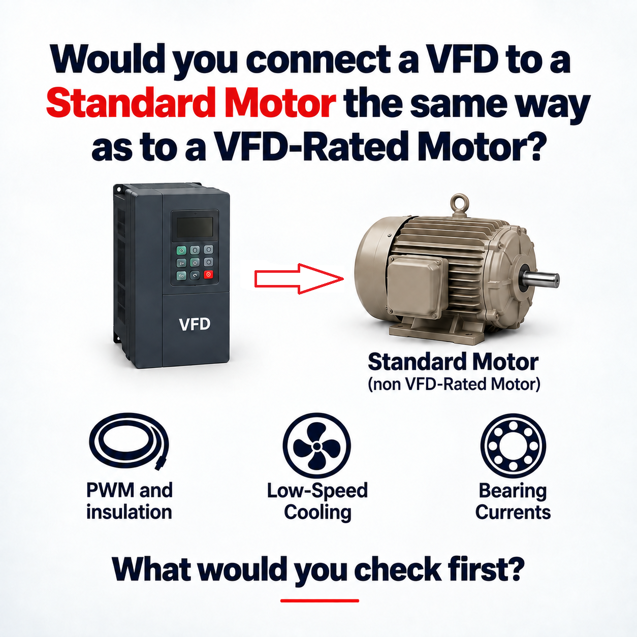
Can a Standard Motor Be Connected to a VFD?
Often yes. A standard three-phase induction motor does not automatically fail when connected to a compatible VFD. Successful operation is possible when the motor and installation meet the application requirements [1].
But “can it run?” and “is the application properly engineered?” are different questions. A brief successful run does not establish suitability for years of PWM exposure or hours of loaded operation at low speed.
The connection diagram may look familiar. The engineering review still needs to cover the motor, drive, cable and operating duty.
1 — PWM and Insulation
A utility-fed motor normally sees an approximately sinusoidal supply. A modern PWM VFD controls voltage and frequency using fast switching pulses; the motor current can be much smoother than the applied voltage.
Fast voltage edges interacting with the cable and motor can produce reflected-wave overshoot at the motor terminals. Longer leads can make these effects more significant, but length alone does not establish the peak voltage or a safe boundary.
Check motor insulation capability, voltage class, age and repair history against the actual supply voltage, cable length, VFD rise time and switching behavior. Thermal insulation class alone does not specify repetitive PWM voltage withstand. Manufacturer limits govern [1].
For the mechanism, see why VFD motor cable length changes voltage stress.
This is a reason to verify compatibility, not a prediction that every standard motor will fail.
2 — Low-Speed Cooling
Many totally enclosed fan-cooled (TEFC) motors have a shaft-mounted fan. Reducing motor speed also reduces fan speed and available self-cooling. Sustained operation matters: passing briefly through a low speed during acceleration is different from remaining there under load for a shift [2].
The load determines how demanding that condition is:
- Variable-torque loads: centrifugal pumps and fans can require sharply less torque and power as speed falls. This often reduces motor heating, but the actual process and operating curve still need checking.
- Constant-torque loads: conveyors or positive-displacement applications may demand substantial torque and current at low speed, even while the motor’s fan delivers less cooling [3].
Low speed does not automatically mean low thermal stress. Compare the required torque and time at each speed with the manufacturer’s continuous and intermittent operating limits [3].
If self-cooling is insufficient, evaluate permitted torque derating, an approved separately powered blower, or a motor designed for the required duty. Check ambient conditions and thermal protection too. ABB’s motor-protection guidance identifies independent cooling and load limitation as possible measures; the correct solution remains application-specific [2].
3 — Bearing Currents
PWM common-mode voltage can couple through a motor’s internal capacitances and create shaft voltage. Under some conditions, voltage across the bearing lubricant film causes discharge current through the bearing. Repeated discharges can produce surface damage and eventually fluting [4].
There are also circulating and shaft-grounding current paths. Motor size, construction, bonding, cable installation and the driven equipment affect which mechanism matters. A quiet first run does not rule out progressive damage.
Follow the motor and drive OEM recommendations. Depending on the mechanism, mitigation may involve improved high-frequency bonding and shielding, shaft grounding, an insulated bearing, or suitable common-mode filtering [4]. These measures need coordinated selection; “add an insulated bearing” is not a universal prescription.
An inverter-duty label does not guarantee that shaft grounding or insulated bearings are included. Check the exact motor specification and installed options. Manufacturer product ranges specify different bearing provisions [5].
4 — Standard Motor vs. VFD-Rated Motor
Inverter-duty or VFD-rated motors are generally designed and specified with drive operation in mind. This may include insulation suited to PWM exposure and a documented speed/torque envelope. The label should lead to supporting data, rather than replace it [5][6].
| Check | Standard motor | VFD-rated / inverter-duty motor |
|---|---|---|
| PWM suitability | Obtain confirmation of permitted VFD operation and insulation capability. | Verify the stated PWM capability against the selected drive and installation. |
| Speed and torque | Do not infer a continuous low-speed rating from the line-frequency rating. | Use the specified operating envelope and required cooling arrangement. |
| Bearing protection | Review OEM recommendations and installed construction. | Check which provisions are included and which remain application-dependent. |
Some general-purpose motors already have documented inverter capability. Conversely, a motor marketed for VFD service is not immune to excessive terminal voltage, inadequate cooling or bearing currents. ABB’s nameplate guidance illustrates why inverter type and constant-torque, variable-torque and constant-power ranges are separate pieces of information [6].
When Should Additional Mitigation Be Evaluated?
Where the documented insulation capability and expected waveform do not align, evaluate an approved dV/dt filter or sine-wave filter with the drive and motor manufacturers. A dV/dt filter treats fast edges; a sine-wave filter more extensively attenuates PWM content. Both have product-specific limits, including cable, current, switching and output-frequency requirements [7].
For the selection process, see output reactors, dV/dt filters and sine-wave filters.
Treat each measure against its purpose: a blower addresses cooling, while shaft grounding or bearing insulation addresses particular current paths. An output filter’s differential-mode voltage performance does not automatically establish its common-mode performance [4][7].
5 — Practical Engineering Checklist
Before connecting an existing standard motor to a VFD, record and verify:
- Motor identity: manufacturer, exact model, nameplate and data sheet; obtain confirmation that VFD operation is permitted.
- Insulation and voltage: documented PWM/voltage capability, actual supply voltage, and motor age, condition or rewind history.
- Drive and motor leads: exact VFD model, manufacturer lead recommendations, actual cable length and construction, and any required output-side mitigation.
- Operating profile: expected speed range and the amount of time spent at low speed, including repeated cycles.
- Load requirement: variable or constant torque, continuous demand, starting torque and overload duty.
- Cooling: motor cooling method, ambient conditions, permitted load/speed envelope and thermal protection; evaluate a separately powered blower when needed.
- Bearing-current control: shaft-voltage recommendations, installed bearing/grounding provisions and the driven-machine connection.
- Installation: protective grounding, high-frequency bonding, shielding and cable termination according to the applicable manuals.
Use this as a review sequence, not a substitute for product documentation. Where the motor’s capability is unknown or the proposed duty exceeds published limits, resolve that gap with the manufacturers before accepting the application.
A VFD Changes More Than Motor Speed
A standard motor can be a suitable choice. An inverter-duty motor can provide a better-defined starting point. Both require an application review.
References
- [1] ABB Technical Guide No. 102 — Effects of AC Drives on Motor Insulation. Background on standard motors, PWM and insulation stress; its historical product limits are not universal current limits.
- [2] ABB — Understanding the effects of variable speed drives on motors. Cooling and load-capacity principles; the page’s hazardous-area product requirements retain their stated scope.
- [3] ABB Technical Guide No. 7 — Dimensioning of a Drive System, load types and motor loadability.
- [4] ABB Technical Guide No. 5 — Bearing Currents in Modern AC Drive Systems, current mechanisms and mitigation.
- [5] ABB Baldor-Reliance — V*S Master, an example of specified inverter-duty insulation, torque capability and bearing provisions.
- [6] ABB — How to Read a NEMA Motor Nameplate, inverter type and operating-range information.
- [7] ABB Technical Note 181 — Selecting and Applying Output Filters, for the covered ACS880 480 V and 600 V drives.