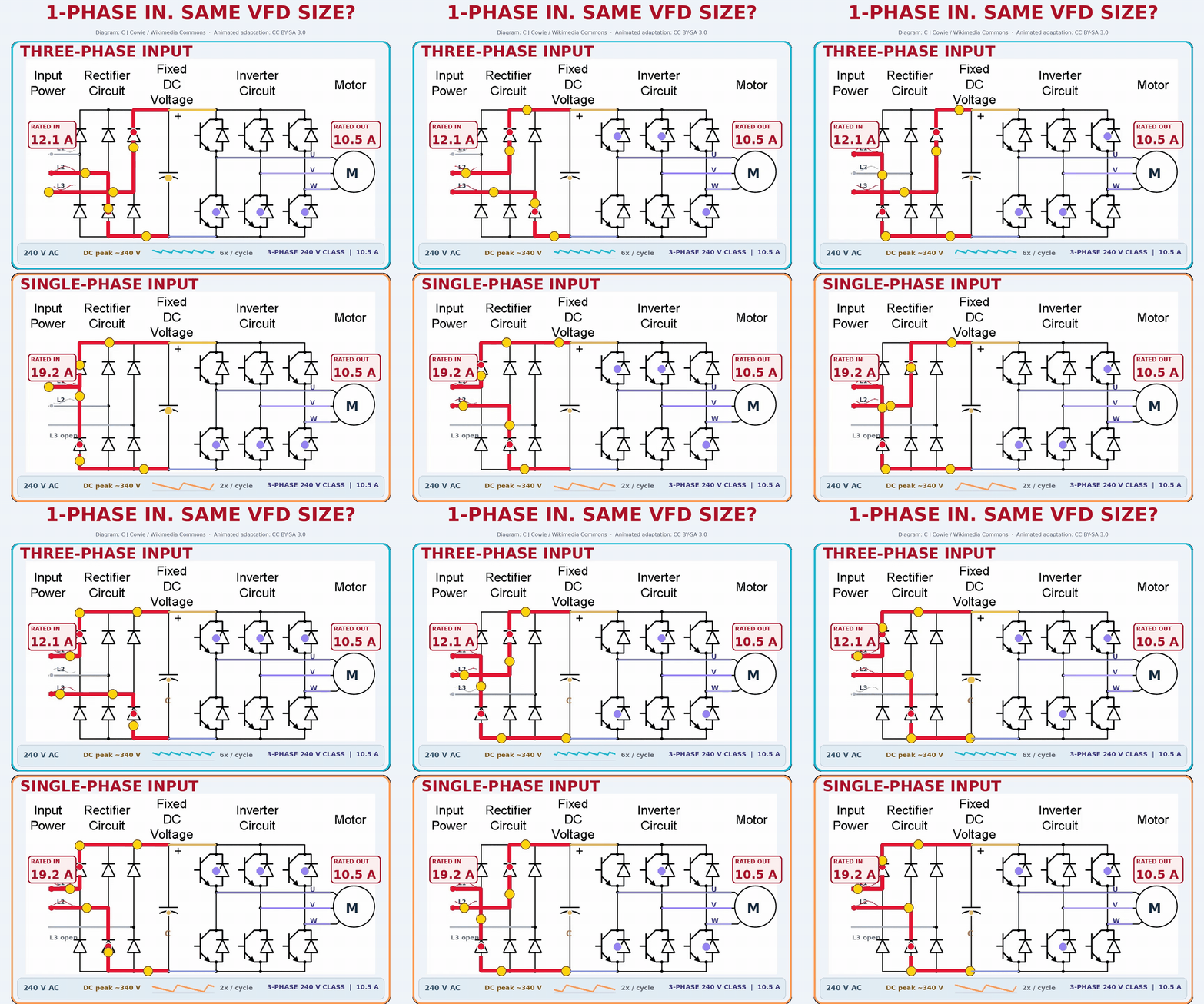
You have a 240 V, three-phase motor with a 10.5 A nameplate current. The available VFD is normally supplied from three-phase power. At this site, however, the available supply is 240 V single-phase. Can we still use a three-phase-output drive? And if so, can we choose the same size we would have used with three-phase power?
The answer depends on the specific drive’s approval and ratings. The motor still needs a suitable three-phase output. The single-phase source will generally supply more line current for the same power, while the VFD’s rectifier and DC link face a different duty. An approved drive may therefore need to be upsized so its allowed output current after single-phase derating still covers the motor.
Follow the Two Paths in the Animation
The upper circuit has three input phases. The lower circuit has only two energized input conductors and an unused third input in the drawing. Both circuits show the same broad sequence:
- The input rectifier converts the incoming AC into a pulsating DC voltage.
- The DC-link capacitor stores energy and reduces the voltage variation between charging peaks.
- Six controlled switches in the inverter synthesize three PWM output phases for the motor.
That last step matters: a single-phase input does not make the output a single-phase motor supply. With an appropriately rated drive, the motor still receives controlled three-phase PWM voltage. The voltage at the inverter terminals is a switching waveform; the motor current can be much closer to sinusoidal because of the motor winding inductance. The GIF slows and simplifies all these events so we can see the current paths. It does not reproduce the switching pattern or internal component ratings of a particular drive.
At 240 V RMS, the sinusoidal supply has a peak of approximately 240 × √2 ≈ 339 V. A capacitor-input DC bus may approach that peak in either arrangement. The bus is not guaranteed to remain at 340 V: diode drops, load, supply impedance and capacitor charging all matter. Nor does the motor receive a constant 340 V DC supply; the inverter turns the DC-link energy into a controlled PWM output.
For a conventional diode front end on a 60 Hz supply, the three-phase rectified voltage has six characteristic peaks per line cycle (360 Hz), while a single-phase full-wave rectified voltage has two (120 Hz). With fewer charging opportunities, the DC-link capacitor must support the load over longer intervals. The illustration shows that difference in timing; its drawn ripple size is a teaching device, not a calculation of a specific capacitor’s actual voltage ripple.
Why the Supply Current Goes Up
Imagine the motor is doing the same work and the VFD is delivering essentially the same output in both cases. The required real power does not disappear when one input phase is missing. With a single-phase supply it has to enter through one line pair instead of being shared across three phases.
For RMS current and true input power factor, the approximate input-power relationships are:
If the real input power, voltage and true input power factor happened to be the same in the two cases, the single-phase line current would be √3 ≈ 1.73 times the three-phase line current. Real VFD input waveforms are nonlinear, so the two true power factors need not be equal. The actual ratio is not a universal 1.73 or 1.8, and it cannot be read directly from the motor nameplate.
Here is one deliberately transparent estimate that produces a value close to the GIF’s single-phase input figure. Assume the motor operates at 240 V, 10.5 A and 0.80 motor power factor; assume 95% VFD efficiency and 0.80 true single-phase input power factor:
Rounded for a conceptual graphic, that is about 19 A; the animation displays 19.2 A. The corresponding operating current with three-phase input would depend on that configuration’s own true input power factor. There is no reason to force it to equal either the 10.5 A motor current or the GIF’s 12.1 A upper input-side label.
The point worth keeping is simple: the same 10.5 A motor can call for substantially more current from a 240 V single-phase source. “A 10.5 A motor” does not mean “a 10.5 A single-phase feeder.”
Why a Three-Phase-Input Drive May Need Upsizing
The DC bus can reach a similar peak voltage with either 240 V supply, so it may look as if nothing important has changed. But a similar voltage peak tells us very little about current and thermal duty.
With single-phase input, more current is concentrated in the conducting rectifier paths, and the DC-link capacitors have a different charging and ripple-current burden. Published guidance from ABB and Schneider Electric both discuss these stresses. A manufacturer may impose a lower permitted continuous output current, require a line reactor or other measures, or prohibit single-phase operation for a particular drive altogether.
That is why simply seeing 240 V on a three-phase-input VFD is not permission to put two wires on its input. First establish that the specific product and voltage class are approved for this supply. Then use its actual single-phase rating or derating method.
The conditional 50% example
Suppose the selected manufacturer’s published instruction explicitly permits single-phase input and leaves only 50% of the drive’s otherwise applicable continuous output-current rating. If the motor needs 10.5 A continuously, the starting arithmetic is:
In this example, 21 A means nominal VFD output-current capability before that 50% derate. After the derate, 21 A × 0.50 = 10.5 A available output. Choose the next published drive size that satisfies the manufacturer’s actual single-phase table, duty class, overload and installation conditions. The ~19 A supply-side estimate is a separate check; it is not a 19 A output-rating recommendation.
This is a conditional worked example, not an ABB part-number selection and not a rule for every three-phase-input drive. ABB’s single-phase application note gives a 50% case for one drive family, while its comparison guide explicitly says that rule does not carry over unchanged to another family. The current manufacturer’s published single-phase output table takes priority over a generic division by two.
| Location | Number in this example | Meaning | Final check |
|---|---|---|---|
| Motor / VFD output | 10.5 A | Three-phase motor current used for continuous output selection. | Motor nameplate, voltage connection, actual load and overload duty. |
| Single-phase supply / VFD input | About 19 A | Illustrative RMS input-current estimate under the stated power-factor and efficiency assumptions. | Published single-phase drive input current, source capability, wiring and protection requirements. |
| Three-phase-input VFD, before derating | At least 21 A output, only in the 50% example | Nominal output rating that would leave 10.5 A after the assumed derate. | Manufacturer approval and its actual single-phase continuous output and overload ratings. |
A Practical Selection Sequence
For a real installation, take these checks in order rather than selecting the VFD from a single ratio:
- Confirm the motor: Read its voltage, full-load current, frequency, winding connection and required torque. A 240 V-class VFD cannot automatically supply a motor’s rated 460 V performance from 240 V input.
- Confirm the supply: Measure the voltage available between the two input conductors and check its permitted range, frequency and available capacity. Two hot legs of a North American 120/240 V split-phase service provide a 240 V single-phase source; they are not two phases of a three-phase source.
- Confirm drive approval: Find the manufacturer’s instructions for that exact drive and voltage class. Check whether single-phase input is allowed, and whether input phase-loss detection or other settings must be configured under those instructions.
- Confirm the drive’s derated output: Compare the published single-phase continuous output rating with the motor’s required current. Include required overload, ambient-temperature, altitude and any other applicable derating in the way the manufacturer specifies.
- Confirm the input side: Check the published single-phase input current or supported supply rating for the chosen larger drive. Size the source, conductors and branch protection from the approved installation instructions and applicable requirements; an estimated 19 A operating current is not itself a protective-device rating.
- Confirm the connection details: Land the two supply conductors on the specified VFD input terminals and follow the manufacturer’s guidance on line reactors, grounding, fusing and start-up. The unused third terminal in the GIF is explanatory, not a universal wiring instruction.
If the drive maker has an approved single-phase-input / three-phase-output product with adequate ratings, its published table may make selection more direct. This note focuses on the situation where the available drive is nominally a three-phase-input model that might be approved for single-phase operation.
Common Questions
Does a single-phase input make the motor output single-phase?
No. For an approved VFD with a three-phase inverter output, the drive can still deliver three controlled output phases to a suitable three-phase motor. The motor-side voltage class and usable output current must meet the application.
Can the two supply wires go to any two of the three input terminals?
Do not infer terminal choice from this diagram. Rectifier paths may look symmetrical, but approved terminal assignments, protection and phase-loss behaviour are product-specific. Follow the selected manufacturer’s single-phase connection instructions.
Is 1.8 × motor current the required VFD size?
No. Around 1.8 × 10.5 A ≈ 19 A is a rough input-line-current illustration under one set of assumptions. A VFD’s nominal output rating is selected from its published single-phase output capability and the motor’s required duty. In the separate 50% derating example, that arithmetic produces 21 A nominal output before selecting an actual drive size.
Is a drive labelled 19 A input automatically large enough?
No. A three-phase nameplate input-current value does not automatically become the allowed single-phase input rating. Nor does an input ampere figure establish the available three-phase output after derating. Both sides must be checked using the approved documentation.
Is 50% derating always the answer?
No. It is documented for some products, while other families have different tables and limits. In one ABB comparison guide, the maker explicitly warns against transferring its 50% rule to the next drive family. An unsupported product cannot be made suitable by choosing an arbitrary larger nameplate.
Engineering Takeaway
For our 240 V, 10.5 A three-phase motor, the single-phase line might carry about 19 A under the stated illustration. That higher input-side demand explains why the original three-phase-input drive selection may need reconsideration; it does not, by itself, select a drive. If the drive is approved for single-phase supply and a documented 50% output-current derate applies, the simple starting requirement is at least 21 A nominal VFD output to retain 10.5 A after derating. The real selection still comes from the specific drive’s published single-phase input rating and derated output rating.
The useful mental picture is one motor, two input arrangements, and two independent sizing checks: can the source and the drive input stage handle the single-phase duty, and can the drive still supply the motor’s three-phase current after derating?
References
- ABB, Single Phase De-rate Operation (technical note, 2014) — a documented 230 V, 50% output-current example and specific connection instructions for the family covered by that note.
- ABB, General Purpose Drives Comparison Guide (Rev C, single-phase selection section) — distinguishes product-specific single-phase output tables from the older 50% rule.
- Schneider Electric, Why is oversizing the drive and using a line reactor required when a three-phase-input drive is operated with single-phase supply? — rectifier current, DC-link ripple and model-specific approval.
- Schneider Electric, Single-phase input to a VFD for a three-phase motor — illustrates that approval, derating and installation requirements vary by drive family.
- C J Cowie, PWM VFD Diagram, Wikimedia Commons — circuit artwork adapted and animated here by ARTPHASE; the GIF is shared under CC BY-SA 3.0. Animated emphasis, labels, colours and the two-input comparison are adaptations; attribution does not imply the original author endorses this example.
