Same THDi, Different Result
Two electrical systems can show exactly the same current THD and still place very different demands on the neutral conductor.
Why? Because THDi tells us how much harmonic RMS current exists—but not which harmonic orders create it.
In a balanced 3-phase, 4-wire system, that distinction matters. Non-triplen harmonics such as the 5th and 7th behave very differently in the neutral from triplen harmonics such as the 3rd.
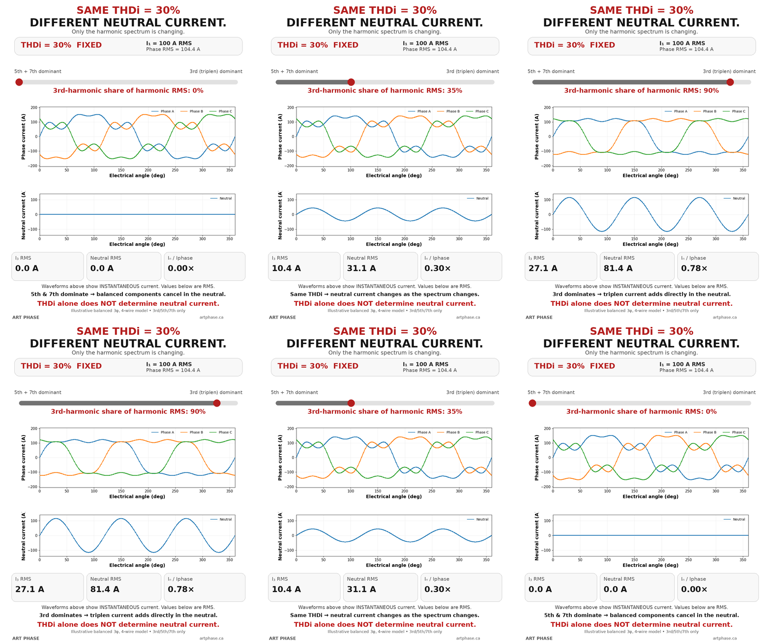
The animation below keeps THDi fixed at 30% while changing only the harmonic spectrum.
What Stays Constant?
The animation represents a simplified, balanced 3-phase, 4-wire system. Each phase has a fundamental current component of:
Current total harmonic distortion is fixed at 30%, so the combined harmonic RMS current remains:
The fundamental and harmonic components are orthogonal RMS components. The total phase RMS current is therefore:
Because both and the combined remain fixed, the total phase RMS current also remains essentially constant throughout the animation.
What Changes?
Only the distribution of that 30 A harmonic RMS current changes.
- At one end, the harmonic content is dominated by the 5th and 7th harmonics.
- As the animation progresses, the share assigned to the 3rd harmonic increases while the other harmonic components adjust so their combined RMS value remains 30 A.
- At the other end, the full 30 A harmonic RMS content is dominated by the 3rd harmonic.
THDi remains 30% at every point. The neutral current changes because the sequence behavior of the harmonic spectrum changes.
Why the 5th and 7th Do Not Accumulate
In the ideal balanced model used here, the three phase currents sum to determine neutral current.
Balanced non-triplen components such as the 5th and 7th retain phase displacement between the three phases. They do not become three in-phase currents in the neutral path, so they do not add arithmetically there.
For the balanced 5th- and 7th-harmonic components in this animation, the resulting neutral contribution is approximately zero. The phase-current waveform can still be visibly distorted and THDi can still be 30%; neither observation, by itself, means that the neutral must carry a large current.
Why Triplen Harmonics Add
Triplen harmonics are harmonic orders that are integer multiples of three:
3rd, 9th, 15th, 21st, …
In a balanced three-phase system, these harmonics behave as zero-sequence components. Their phase relationship makes the corresponding phase components in phase with one another in the neutral conductor. They therefore add instead of cancelling.
For the balanced 3rd harmonic:
When the three phase magnitudes are equal:
The same principle applies to other balanced triplen orders. Their actual contribution depends on the measured or predicted magnitude of each harmonic order, not on THDi alone.
Numerical Example at the 3rd-Harmonic End
At the fully 3rd-harmonic-dominated end of this specific animation:
The total phase RMS current is still approximately 104.4 A, so:
This is a result for the stated spectrum and assumptions. It does not mean that 30% THDi universally produces 90 A of neutral current or an ratio of 0.86.
Case A vs Case B
| Quantity | Case A: mainly 5th + 7th | Case B: mainly 3rd |
|---|---|---|
| THDi | 30% | 30% |
| Combined harmonic RMS | 30 A | 30 A |
| Total phase RMS | Approximately 104.4 A | Approximately 104.4 A |
| Neutral behavior | Balanced 5th and 7th components do not accumulate; their neutral contribution is approximately zero in this model. | Balanced 3rd-harmonic components add in the neutral. |
| Neutral RMS at the illustrated endpoint | Approximately 0 A from the modeled balanced components | Approximately 90 A |
| Approximately 0 | Approximately 0.86 |
Same THDi. Completely different neutral-current demand.
Instantaneous Current vs RMS Current
The animation’s plotted waveforms show instantaneous current. The numeric current values shown in the labels and calculations are RMS values.
Those are not the same quantity. A 100 A RMS sinusoidal fundamental has a peak value of:
Adding harmonic components changes the instantaneous waveform further. It is therefore normal for the plotted phase current to exceed 100 A at some electrical angles even though the fundamental component is specified as 100 A RMS. That visual behavior is not an error.
Practical Engineering Interpretation
High neutral current is especially relevant in 3-phase, 4-wire systems that supply substantial single-phase nonlinear loading. Depending on the equipment and its input topology, examples can include electronic power supplies, office and IT loads, certain lighting loads, UPS input stages, and other single-phase rectifier-type loads.
That does not mean every modern electronic load creates severe neutral current. The actual result depends on the aggregated phase loading, harmonic spectrum, diversity, system impedance, and operating state.
It is also important not to transfer the conclusion automatically to VFD loads. A conventional balanced three-phase 6-pulse VFD commonly produces characteristic harmonics such as the 5th, 7th, 11th, and 13th. These can create significant THDi, but they are not triplen harmonics. High THDi from a balanced three-phase VFD load therefore does not automatically imply severe neutral-current accumulation.
For a related waveform-level example of harmonic compensation, see how an active harmonic filter cancels selected VFD harmonics.
Do Not Turn the Ratio into a Sizing Rule
The animation does not establish a universal relationship between neutral-conductor size and phase-conductor size. It isolates one electrical behavior so the effect of moving harmonic RMS content into the 3rd harmonic can be seen clearly.
Key Takeaway
THDi is an important power-quality metric, but by itself it cannot predict neutral current.
For neutral-current assessment, the harmonic spectrum matters—especially the magnitude of the triplen harmonics. The same THDi can represent two very different electrical conditions.