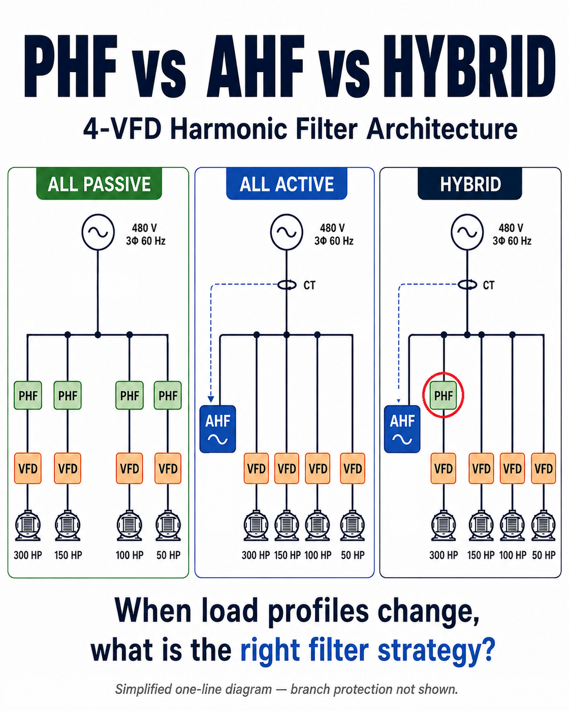
The Engineering Question
A plant has four conventional 6-pulse VFDs on the same 480 V bus:
- 300 HP
- 150 HP
- 100 HP
- 50 HP
The obvious harmonic-mitigation choices are usually presented as a two-way decision:
Passive harmonic filters (PHFs) or an active harmonic filter (AHF).
But a multi-drive system creates a third possibility:
Use passive filtering where the harmonic burden is large and predictable, and active filtering where it is variable.
That leads to the real design question explored here:
Should all four drives use dedicated passive filters, should one central active filter handle the bus, or should the system use a hybrid of both?
The Example System
For a representative 480 V drive family, the approximate rated currents used in this study are:
| VFD Rating | Representative Rated Current |
|---|---|
| 300 HP | 361 A |
| 150 HP | 180 A |
| 100 HP | 124 A |
| 50 HP | 65 A |
These values are consistent with published 480 V ratings for the ABB ACS580 family and are used only to establish a realistic current scale for the case study.
The percentage loading in this article represents approximate electrical utilization for screening. It is not a speed command and it should not be interpreted as an exact motor-power relationship.
One Plant, Three Operating States
The drives are not assumed to sit at one fixed load all day. The plant moves through three operating snapshots:
| VFD | Low Demand | Normal Production | Peak Production |
|---|---|---|---|
| 300 HP | 45% | 70% | 90% |
| 150 HP | 30% | 55% | 85% |
| 100 HP | 15% | 40% | 80% |
| 50 HP | OFF | 25% | 80% |
The corresponding screening currents are approximately:
| VFD | Low Demand | Normal Production | Peak Production |
|---|---|---|---|
| 300 HP | 162 A | 253 A | 325 A |
| 150 HP | 54 A | 99 A | 153 A |
| 100 HP | 19 A | 50 A | 99 A |
| 50 HP | 0 A | 16 A | 52 A |
| Total | 235 A | 418 A | 629 A |
This changing load profile is the reason the filter architecture matters. At peak production almost every drive is heavily loaded. At low demand, the same installed VFD system is highly diversified.
Architecture 1 — All Passive
The first option gives every VFD its own line-side PHF:
480 V Bus → PHF → VFD → Motor
repeated four times.
A representative 480 V Matrix AP selection illustrates the hardware scale:
| VFD | Representative PHF Current Rating |
|---|---|
| 300 HP | 403 A |
| 150 HP | 208 A |
| 100 HP | 128 A |
| 50 HP | 66 A |
The important point is not the brand. It is the architecture: four independently sized harmonic-mitigation systems are installed because there are four VFD branches.
Where all-passive is strong
At peak production the PHFs are operating around 80–90% of their associated VFD loading. This is exactly where a properly selected passive harmonic filter can be very effective.
For example, MTE publishes a Matrix AP performance guarantee of 5% maximum THID at full load and 8% maximum THID at 30% load, subject to its stated system conditions.
So the all-passive option should not be dismissed as a weak solution. For predictable, heavily loaded branches it can be an excellent one.
Where the question becomes more interesting
At low demand the branch utilization becomes:
- 300 HP branch: 45%
- 150 HP branch: 30%
- 100 HP branch: 15%
- 50 HP branch: OFF
The 100 HP branch is now below the 30% point covered by the example performance guarantee, while the 50 HP branch produces no drive harmonics at all.
That does not mean the PHF automatically performs badly at light load. Modern passive filters can maintain good harmonic performance over a broad range. It means the design must be evaluated across the operating envelope rather than judged only at full load.
Passive filters can also include capacitive elements, so light-load reactive behavior and capacitor switching may become part of the design. Some commercial PHFs provide capacitor-disconnect or load-controlled contactor options specifically for this reason.
Architecture 2 — All Active
The second option leaves the four VFD branches unfiltered locally and connects one AHF in parallel with the 480 V bus.
The AHF measures harmonic current through its CT arrangement and injects compensating current. Unlike a branch PHF, its compensation effort can follow the aggregate harmonic demand of the bus as operating conditions change.
That makes load diversity valuable.
A preliminary compensation-current estimate
For a simple screening comparison, assume:
- conventional 6-pulse VFD input current distortion of approximately 40% THDi before external harmonic filtering,
- a screening target of approximately 5% residual bus THDi,
- and scalar aggregation for a deliberately simple first-pass estimate.
The required AHF compensation current is then approximated as:
This produces:
| Operating State | Approx. Bus Current | Preliminary AHF Compensation |
|---|---|---|
| Low Demand | 235 A | ≈ 82 A |
| Normal Production | 418 A | ≈ 146 A |
| Peak Production | 629 A | ≈ 220 A |
The important design point is that the AHF follows the actual harmonic compensation current, not the sum of the VFD horsepower ratings.
At low demand it may use only a fraction of its available capacity. At peak production it must still be capable of meeting the worst required operating condition.
Modular AHF capacity matters
A 220 A requirement does not automatically mean that a single 300 A AHF must be installed.
Several commercial AHF platforms support parallel modular operation. Where the selected 480 V product family allows it, the installed capacity can be assembled close to the calculated requirement — for example, approximately 225 A rather than jumping automatically to a 300 A single unit.
The exact combination is manufacturer-specific and must be checked for system voltage, parallel-control architecture, enclosure limits, derating and redundancy philosophy.
Architecture 3 — Hybrid
The third option separates the harmonic burden into two different types.
The 300 HP drive is the largest load and remains significant in all three operating states:
45% → 70% → 90%
So it receives a dedicated PHF.
The remaining drives are much more variable:
- 150 HP: 30% → 55% → 85%
- 100 HP: 15% → 40% → 80%
- 50 HP: OFF → 25% → 80%
Those branches remain directly connected to the bus, while a central AHF compensates the remaining bus harmonic current.
This is not simply “put the passive filter on the largest drive.”
The reason the 300 HP branch is selected is that it is both large and comparatively predictable.
What happens to AHF capacity?
For a conservative screening calculation, assume the dedicated PHF leaves 8% residual THDi on the 300 HP branch while the other three unfiltered drives remain at the 40% screening assumption.
The pre-AHF harmonic-current estimate is:
Subtracting the same 5% residual-bus target gives the following preliminary AHF requirement:
| Operating State | All-Active AHF | Hybrid AHF |
|---|---|---|
| Low Demand | ≈ 82 A | ≈ 30 A |
| Normal Production | ≈ 146 A | ≈ 65 A |
| Peak Production | ≈ 220 A | ≈ 116 A |
At peak production, local mitigation on the dominant 300 HP branch reduces the preliminary active-compensation requirement from about 220 A to 116 A.
That is a reduction of roughly 104 A of active compensation burden in this simplified model.
With a modular AHF platform, the conceptual installed capacity could therefore move from approximately 225 A in the all-active case to approximately 125 A in the hybrid case, subject to the actual manufacturer’s available 480 V modules and selection rules.
The Three Architectures Side by Side
| Criterion | All Passive | All Active | Hybrid |
|---|---|---|---|
| Local PHFs | 4 | 0 | 1 |
| Central AHF | None | ≈ 220 A calculated / modular selection required | ≈ 116 A calculated / modular selection required |
| Peak-load harmonic capability | Strong | Strong when correctly sized | Strong when correctly sized |
| Adaptation to load diversity | Branch-specific | Excellent | Excellent |
| Distributed hardware | Highest | Lowest | Intermediate |
| Branch independence | Excellent | Lower | Intermediate |
| Light-load capacitor considerations | Four PHF branches to review | None from PHFs | One PHF branch to review |
| Future expansion | Usually branch-by-branch | Potentially modular | Potentially modular |
| Initial cost | Quote-dependent | Quote-dependent | Quote-dependent |
Reliability Is More Nuanced Than “One AHF = One Point of Failure”
A distributed PHF arrangement has a clear advantage: a problem on one filter branch does not automatically remove harmonic mitigation from every drive.
A central AHF concentrates more of the harmonic-mitigation function in one location.
However, modern AHF systems can be modular. If several modules operate in parallel, the loss of one module may leave partial compensation capacity available rather than reducing the entire system to zero.
The actual failure behavior depends on the product architecture, common controls, bypass philosophy, protection scheme and the number of installed modules.
The hybrid arrangement sits between the two extremes. If the central AHF is unavailable, the largest 300 HP nonlinear load still retains its local PHF, although the remaining bus may no longer meet the intended harmonic target.
Which Architecture Wins This Case Study?
There is no universal winner between PHF and AHF.
But for this specific load profile, the hybrid arrangement is the most interesting engineering fit.
Why?
The four VFDs naturally separate into two different harmonic burdens:
Predictable dominant burden
The 300 HP drive remains materially loaded across all three operating states.
A dedicated PHF can remove much of that large, relatively predictable harmonic contribution locally.
Variable diversified burden
The 150 HP, 100 HP and 50 HP drives move from very light or off conditions to heavy production loading.
A central AHF can follow the changing aggregate harmonic demand rather than installing a dedicated full branch filter on each of those drives.
That leads to the central finding of the study:
When the Result Would Change
The hybrid answer is not a rule that says “put a PHF on the largest VFD.”
The decision could change significantly if:
- the 300 HP drive itself cycled widely or spent long periods at very light load,
- all four drives operated near high load most of the time,
- the plant had many more small nonlinear loads,
- the AHF had to provide substantial reactive-power or unbalance compensation in addition to harmonics,
- source impedance or background voltage distortion changed the harmonic behavior,
- physical space strongly favored one architecture,
- first cost or lifecycle cost strongly favored another,
- or a future expansion plan changed the expected bus loading.
If all four VFDs routinely operated at 80–100% load, the all-passive architecture could become much more attractive.
If the plant load were highly dynamic with frequent additions and removals of nonlinear loads, centralized active filtering could become more attractive.
The architecture should follow the system behavior.
IEEE 519 and the 5% Number
The 5% residual THDi used in this article is a screening target for comparing architectures. It is not a claim of IEEE 519 compliance.
IEEE 519 evaluates harmonic current limits at the point of common coupling using TDD and limits that depend on the short-circuit ratio Isc/IL. Voltage distortion at the PCC must also be checked.
Therefore a final study should establish:
- the defined PCC,
- available short-circuit current and source impedance,
- maximum demand load current,
- individual harmonic current spectrum,
- background voltage distortion,
- voltage THD and individual voltage harmonics,
- TDD at the PCC,
- transformer and generator operating conditions where applicable,
- and the project or utility harmonic limits.
Final Design Lesson
A multi-VFD harmonic problem should not be reduced to a product question:
“Should I use an AHF or a PHF?”
A better sequence is:
- Identify the nonlinear loads and their actual operating profiles.
- Separate large predictable loads from highly variable loads.
- Estimate the harmonic burden in low, normal and peak operating states.
- Compare distributed passive, centralized active and hybrid architectures.
- Perform manufacturer-specific harmonic sizing and a PCC compliance study before final selection.
In a system with load diversity, installed horsepower alone does not tell the full story.
The harmonic-mitigation architecture may be better determined by how the loads behave over time.
References
References
- IEEE Std 519 — Harmonic control in electric power systems; use the edition and limits applicable to the project.
- ABB ACS580 published 480 V drive ratings and ABB technical guidance on harmonics in drive systems.
- MTE Corporation — Matrix AP Harmonic Filter performance guarantee and 480 V product-selection data.
- Sinexcel — Active Harmonic Filter product literature describing modular AHF capacities and parallel operation; verify the applicable voltage-specific product family for a 480 V installation.
- Manufacturer-specific AHF sizing tools, CT application guidance and project-specific source / PCC data for final design.