Why Parallel Passive Filters?
For a small or medium VFD, filter selection is usually direct: determine the drive input current, choose the correct voltage and current rating, and verify the manufacturer’s installation and performance requirements.
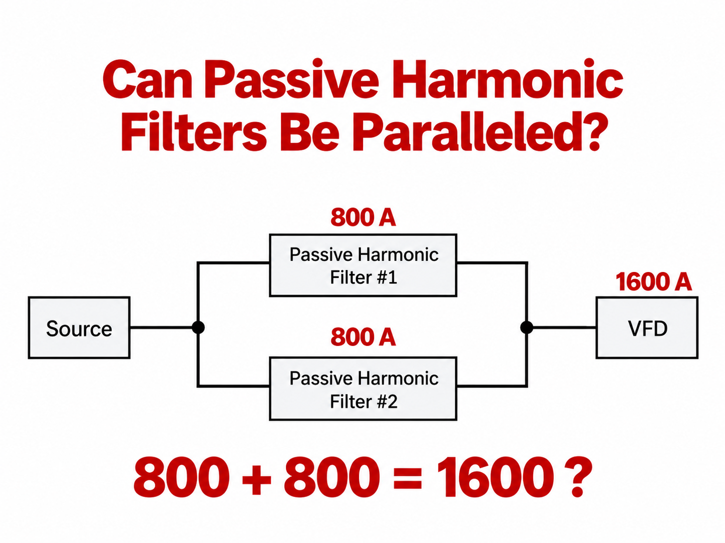
A large VFD can exceed the practical rating of one standard passive harmonic filter. Multiple filters in parallel may then provide the required current capacity:
Source → parallel passive-filter branches → common output → VFD
These filters are in the VFD power path. This is not the same arrangement as an active harmonic filter connected as a shunt compensating device on a bus.
Can They Actually Be Paralleled?
Yes—when the manufacturer explicitly supports the arrangement and its instructions are followed.
MTE’s application note Matrix AP Recommendations for Paralleling Filters permits Matrix AP units to be paralleled to increase current or power capacity. It calls for exact matching catalog numbers, apart from specified master/slave configurations, and says not to mix voltage, frequency, or current ratings. It also limits a bank to three parallel units.
The practical interpretation is simple: treat the units as a matched filter bank, not as unlike filters whose ratings happen to total the desired current.
The Combined Rating Must Be Derated
For parallel MTE Matrix AP configurations, the application note limits loading to 90% of the sum of the filter nameplate ratings:
MTE states that this margin allows for slight variations caused by manufacturing tolerances. Two physical filters are not assumed to share current perfectly enough to use 100% of their arithmetic sum continuously.
Example: Two 800 A Filters for a 1600 A VFD
Suppose the required VFD input current is 1600 A, and two matching 800 A filters are available.
At first glance, the filters appear to match the load exactly. Under the MTE Matrix AP rule, however, the usable rating is:
Although the nameplates total 1600 A, the usable combined rating under this manufacturer-specific guideline is only 1440 A. Two 800 A Matrix AP filters would therefore not be sufficient for the stated 1600 A requirement.
The lesson is broader than this example: nameplate arithmetic alone is not enough when passive harmonic filters operate in parallel.
MTE’s Published 1270 A Example
MTE’s note gives a similar example for a system requiring 1270 A. Two 636 A units appear to total 1272 A, but they fail after the required factor is applied. MTE instead shows two 786 A units.
| Option | Nameplate Sum | Usable Rating at 90% | Result for 1270 A |
|---|---|---|---|
| 2 × 636 A | 1272 A | 1144.8 A | Not sufficient |
| 2 × 786 A | 1572 A | 1414.8 A | Sufficient for current sizing |
This comparison comes directly from MTE’s parallel-filter application guidance. “Sufficient” here addresses the parallel-filter current calculation only; it is not final approval of the complete installation.
Current Rating Is Only One Check
Once the arithmetic works, the design is not finished. Verify each of these items against the filter documentation, VFD instructions, and applicable electrical codes.
Matching filters
Confirm compatible voltage, frequency, current, options, and catalog configuration. Matrix AP units normally require matching catalog numbers.
Number of units
The MTE guidance used here permits no more than three filters in parallel.
Fusing and conductors
MTE recommends individual, same-type fuses for parallel filters and describes limited conditions for common input fusing of panel-mount arrangements. Filter fusing and VFD input fusing must both be verified. Size conductors, terminals, and common buswork for the actual current carried.
Thermal protection
MTE says each filter’s thermal switch should be incorporated into the drive control circuit so an over-temperature condition in any one unit shuts the system down.
Switching coordination
Some Matrix AP options use capacitor contactors. Where fitted, their control must follow MTE’s parallel-operation instructions; the permitted arrangement depends on the option configuration.
Drive requirements
The filter does not replace the VFD manufacturer’s fuse limits, conductor requirements, installation instructions, or applicable codes.
A Practical Workflow
- Determine the actual required VFD input current.
- Confirm that the filter manufacturer permits parallel operation.
- Select matching filter units.
- Apply the manufacturer’s parallel derating or sizing method.
- Verify that usable capacity exceeds the required input current.
- Check fusing, buswork, conductors, thermal protection, and switching.
- Validate the arrangement against both filter and VFD documentation.
The Key Takeaway
Parallel passive harmonic filters can serve very large VFDs when one suitably rated filter is unavailable. But their usable capacity may be less than the sum of their nameplates.
For the MTE Matrix AP example in this note:
That is below a 1600 A requirement, so the proposed bank is undersized.
Reference
References
- MTE Corporation — Matrix AP Recommendations for Paralleling Filters (official application note).
The matching-filter requirement, three-unit maximum, 90% combined-rating limit, 1270 A example, fusing guidance, and over-temperature guidance discussed above come from this MTE application note.