The Key Distinction
A 500 A Active Harmonic Filter does not normally draw 500 A of real current from the utility simply because its nameplate says 500 A.
The 500 A rating refers primarily to the filter’s compensation-current capability: the maximum corrective current that its inverter can generate and inject at the point of common coupling to cancel unwanted harmonic components of the load current.
This distinction is one of the most important concepts when understanding an Active Harmonic Filter.
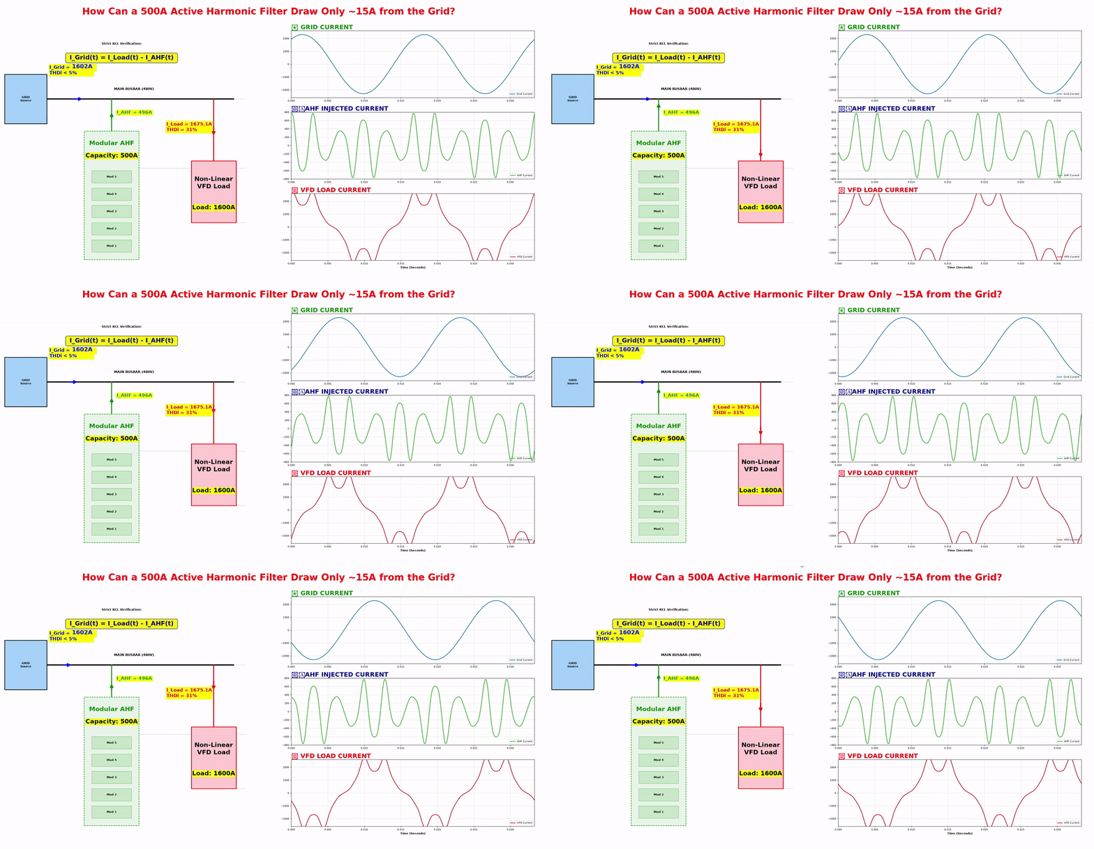
In the example shown in the animation, we will use a large nonlinear VFD load and follow the current mathematically from the load side back toward the utility.
Example Operating Point
Consider the following illustrative case:
- System voltage: 480 V, three-phase
- Fundamental load current: approximately 1600 A
- Initial load-current distortion: approximately 31% THDi
- Total load RMS current: approximately 1675.1 A
- AHF compensation current: approximately 496 A
- AHF rated capacity: 500 A
- Target utility-side distortion: approximately 5% THDi
- Resulting utility RMS current: approximately 1602 A
These values are intentionally selected so the relationship between fundamental current, harmonic current, total RMS current, and AHF compensation can be seen clearly.
1. Where Does the 496 A Harmonic Current Come From?
THDi is defined relative to the fundamental current:
where:
For an approximately 1600 A fundamental current and 31% THDi:
So the nonlinear VFD load contains approximately 496 A RMS of combined harmonic current.
The total RMS current is not obtained by simply adding 1600 A and 496 A. Because the fundamental and harmonic components are orthogonal RMS components:
therefore:
This explains the 1675.1 A load-current value shown in the animation.
2. Recovering the Fundamental Current from the RMS Values
We can also work backward from the measured total RMS current:
Using the values in this example:
This 1599.98 A value is the fundamental current, not the final total RMS current seen by the utility. That distinction is important.
3. What Happens When the AHF Reduces THDi from 31% to 5%?
The goal of the Active Harmonic Filter in this example is not to remove the 1600 A fundamental load current. The motor/load still requires approximately the same fundamental current.
The AHF instead injects an opposing harmonic current waveform so that most of the load-generated harmonic current does not propagate upstream into the utility.
If the utility-side target is approximately 5% THDi:
The utility therefore still carries approximately 1600 A fundamental current plus only about 80 A RMS of residual harmonic current. The resulting total grid RMS current becomes:
This is why the animation shows approximately:
Load: 1675.1 A RMS at ~31% THDi
becoming:
Grid: ~1602 A RMS at ~5% THDi
after harmonic compensation.
Notice that the AHF may be injecting nearly 496 A of corrective current, while the total RMS current drawn from the source only decreases by about 73 A. That is not a contradiction.
The 496 A represents harmonic compensation, not 496 A of ordinary fundamental load current being removed.
4. Why Can’t We Simply Subtract RMS Currents?
At every instant, Kirchhoff’s Current Law still applies:
This is an instantaneous waveform relationship. However, it is generally incorrect to write:
because RMS magnitudes lose the phase, frequency, and waveform information required for direct scalar subtraction.
Harmonic components at different frequencies are combined using root-sum-square relationships, not ordinary arithmetic subtraction. This is why 1675.1 A − 496 A is not the grid RMS current.
5. Where Does the AHF Get Almost 500 A of Compensation Current?
The AHF contains a power-electronic inverter, semiconductor switches, a DC-link capacitor, filtering inductors/reactors, sensing circuitry, and a controller.
The controller continuously measures the load or source current, identifies the unwanted harmonic components, and commands the inverter to generate an opposing current waveform. The inverter then exchanges electrical energy with the AC system through its DC link and switching bridge.
The DC-link capacitor is important, but it should not be thought of as a battery continuously supplying hundreds of amperes of real power. Instead, the inverter synthesizes the required compensating waveform and exchanges instantaneous energy with the AC network while the DC-link voltage is regulated around its target value.
For harmonic cancellation, much of the compensation current is therefore not associated with a large continuous transfer of real energy from the utility into the AHF. The utility mainly needs to provide the AHF’s real internal losses and the small amount of real power required to maintain the DC-link voltage.
6. Why Can a 500 A AHF Draw Only About 15 A of Real Input Current?
Consider the 500 A, 480 V three-phase AHF in this example. Its current rating corresponds to an apparent-power capability of approximately:
Now assume, for this simplified engineering example, that the AHF’s total internal losses are approximately 3% of rated apparent-power capability.
This 3% figure is only an illustrative engineering assumption. Actual losses depend on the specific manufacturer, topology, switching frequency, loading, ambient conditions, cooling system, and operating point.
Using the 3% assumption:
If the filter draws this real power from a 480 V three-phase system at approximately unity power factor:
Therefore, it is entirely reasonable in this simplified example for a 500 A compensation-rated AHF to inject hundreds of amperes of harmonic correction while requiring only approximately 15 A of real input current to cover its own losses.
This is the key point behind the title: 500 A compensation capability does not mean 500 A of continuous real-power consumption.
7. Where Does the Real Power Actually Go?
The main 1600 A fundamental current continues to deliver real power to the VFD-driven load. The AHF is not supplying the motor’s main operating power. Its primary role is to reshape the current seen by the source.
The AHF real-power requirement is mainly associated with:
- semiconductor conduction losses,
- switching losses,
- reactor and magnetic losses,
- DC-link regulation,
- cooling fans, and
- control electronics.
That is why the real input current associated with the filter itself can be very small compared with its compensation-current rating.
8. What the Animation Is Showing
The animation combines three current waveforms:
VFD Load Current
The nonlinear current demanded by the VFD load, containing the fundamental plus substantial harmonic content.
AHF Injected Current
The corrective waveform produced by the Active Harmonic Filter to oppose the unwanted harmonic components.
Grid Current
The current remaining upstream after the load current and AHF compensation waveform combine according to KCL.
In this example:
The result is a source current that is much closer to sinusoidal even though the nonlinear load itself has not changed.
Engineering Takeaway
A large AHF current rating can initially look like a large additional electrical load. It is not.
The nameplate current describes how much corrective current the inverter can synthesize, not how much real current the filter continuously consumes.
For the illustrative case in this Note:
Before compensation
After compensation
while the AHF itself may require only approximately:
of real input current under the assumed 3% internal-loss example.
The AHF is therefore better understood as a controlled current-shaping power-electronic converter, not as a conventional 500 A load.